
Navigation
Menu
Center-fed Bent-Dipoles
Horizontal Lateral
Vertical
- OCF
Slow-Wave
Other Topics
Home
 What happens
if...
What happens
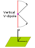
if...You Bend a Vertical Dipole
into a "V"?
The computer model for this study bends the antenna in the middle by any angle from vertical. Starting with our standard vertical dipole with the feed point 1/2 WL above average ground, the study is to increase the V-angle in 15° increments and measure the changes. The results are summarized in Figure 1 and Figure 2 below.
4NEC2 Antenna Model: Here
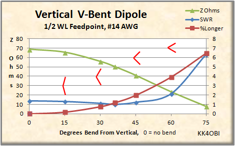
Figure 1
A graphic indication of the V-bend is shown in red.
In general, as the V becomes
narrower, the antenna impedance (green line) goes
down and passes through the 50 Z Ohm point
around 36° from vertical. This could be useful for matching a coaxial
cable. The SWR (blue line) will
likewise go down slowly until it passes the 50 ohm point and then
rise rapidly.
When a resonant vertical dipole is bent into a V-shape it becomes electrically shorter top to bottom. The frequency rises. To maintain the desired frequency, the length of the radiating elements must be made some percentage longer (Red line). For example, at the 50 Z Ohm point the the antenna is 1.17 % longer.
When a resonant vertical dipole is bent into a V-shape it becomes electrically shorter top to bottom. The frequency rises. To maintain the desired frequency, the length of the radiating elements must be made some percentage longer (Red line). For example, at the 50 Z Ohm point the the antenna is 1.17 % longer.
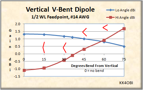
Figure 2
A graphic indication of the V-bend is shown in red.
In Figure 2, gain is the main
story. The desired low angle dBi Gain for DX
becomes gradually weaker as the V-bend increases (Blue line).
There is
no V-beam gain effect as touted in various ham radio articles.
(Perhaps myths of gain from half-wave V-antennas could be an echo from multi-wavelength Vee and Rhombic antennas that so dominated radio up into the 1950's.)
As the V angle increases, high angle gain increases at 45° to 60° above horizontal. It goes from nothing to become a dominant factor in the radiation pattern (Red line). This effect could be useful for NVIS work to contact stations a relatively short distance away.
Another way of looking vertical V-dipole is to think of the polarization of the antenna becoming more horizontal as the V increases When the included angle is less than 90°, radiation becomes dipole-like with gain developing to the sides of the V. At 60° from vertical (which is 60° included angle), the High Angle dBi Gain to the side, slightly exceeds the Low Angle (DX) dBi Gain.
To make clear the change to High Angle dBi Gain with increasing V-angles, consider the following far field radiation graph and 3D flyover views at 0°, 30° and 60° Bend.
 Figure
3
Figure
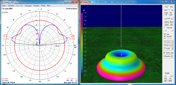
3Standard half-wave vertical center-fed dipole
In Figure 3 the maximum gain is1.33 dBi is at the low angle of 15° above horizontal (purple/red colorization). This is why the vertical antenna is preferred for long distance communications (DX). The high angle lobe at 35° - 40° from vertical is weak... a negative 1.08 dBi gain (green/blue colorization).
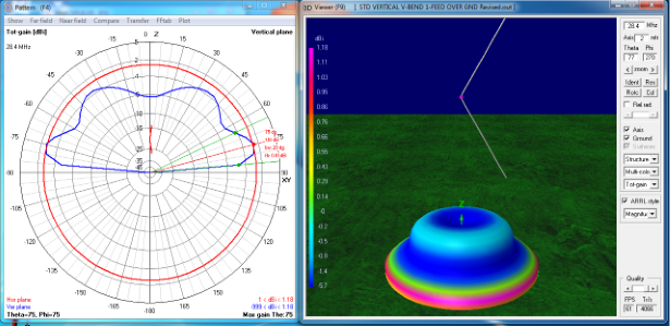
Figure 4
Standard half-wave vertical center-fed dipole bent 30° from vertical.
Standard half-wave vertical center-fed dipole bent 30° from vertical.
In Figure 4 the maximum gain at the 15° low angle (purple/red colorization) is less, 1.18 dBi, down from 1.33 dBi. More noticable is the filling in of the central radiation null and the increase in vertical radiation pattern from negative 1.08 dBi to negative 0.4 dBi at 35°- 40° from vertical. Note that the radiation pattern is circular. There is no hint of directionality.
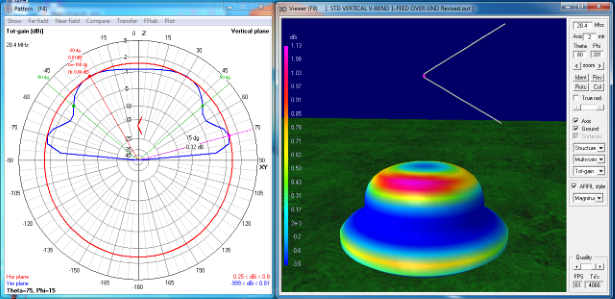
Figure 5
Standard half-wave vertical center-fed dipole bent 60° from vertical.
Standard half-wave vertical center-fed dipole bent 60° from vertical.
In Figure 5, note the derby hat shape. The maximum gain is now in the high angle radiation (purple/red colorization). In particular observe that this radiation is directed to the sides of the V which is at right angles to the conjectured V-beam effect. In a similar manner, the low angle radiation (Yellow band) also favors the sides of the V . Interestingly, the hi angle gain of 0.93 dBi slightly exceeds the low angle gain of 0.81 dBi.
A V-angle greater than 60° continues to increase the high angle gain directed to the sides and decreases the low angle gain... but high SWR becomes a problem.
A reminder about elevation. The study of the Vertical Standard Dipole shows that the upward reflected radiation adds a ring (lobe in crossection) for each half-wave increase in feed point height. This elevation effect and the increasing high-angle radiation should be a consideration in this bent antenna design and placement.
Dick Reid, KK4OBI at QSL.net