
Navigation
Menu
Center-fed Bent-Dipoles
Horizontal Lateral
Vertical
- OCF
Slow-Wave
Other Topics
Home
It is obvious that there is some point between straight and a 90� L where the impedance is 50 Ohms. Up to this point the data presented relates to fine tuning by angle of bend. Now we look at fine tuning by changing the feed point.
The length of a straight wire, including feed-point gap, defines resonant frequency. No matter where you put the feed point, the frequency remains essentially the same until very close to the ends. The characteristic that changes with feed point is impedance... away from the center, it goes up. Based on this, finding the 50 Ohm sweet spot leads to things like the Gamma match, Delta match, Beta Match, J-pole match, etc.
To model the effect on impedance with feedpoint, an antenna model of a dipole was developed where the velocity factor of the wire could be found by optimization. Having that, the feedpoint is treated as a ratio where center feed for that wire is 0.5 ratio. The study then reduces the ratio value in small decrements to find the impedance at each point.
4NEC2 Antenna Model: Here
In Figure 1 following, let us take a look at the effect on impedance caused by off-center feed.
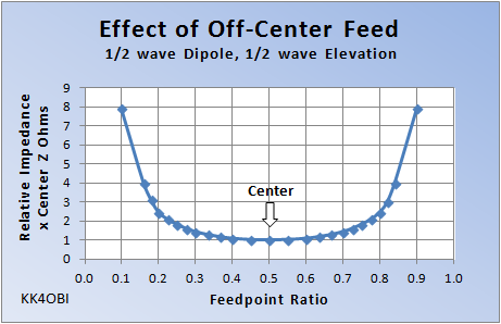
Figure 1
The impedance change is symmetrical. At ratios of 0.25 or 0.75, the the center impedance will rise to be about twice. If the center was at 25 Ohms, it will then be around 50 Ohms. A choke balun is advised.
With this principle in mind, wire antenna modeling is a quick way to find out...
What happens when you...
Change the Feed-point of an L-antenna?
Change the Feed-point of an L-antenna?
To answer this question, an L-Antenna model was developed where the horizontal-to-vertical ratio could be varied. The study was to vary the bend ratio in 0.05 steps around the 0.50 center ratio.
4NEC2 Model: Here
The results are shown in Figure 2 below.
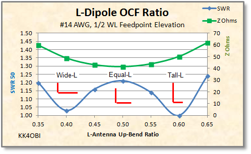
Figure 2
A representation of the antenna configuration is shown in red.
As the up-bend ratio changes, here is a close look at what happens to impedance (Green line) around the center of a resonant L-dipole.
Looking at SWR (Blue line), You see that as the feed-point moves away from the center, the impedance falls. At 0.6 ratio there is a perfect 50 Ohm match. The vertical arm is tall. The antenna becomes more like a vertical with one tuned radial or counterpoise.
Conversely, at the 0.4 ratio the match is very good but not perfect because of greater interaction with ground. The horizontal arm is now long making the antenna relatively wide. The antenna becomes more like a dipole with one end bent up.
Reminder: If you do preliminary tuning near ground, review the impedance changes by "Wavelengths Over Ground" found in "Menu, Horizontal, Standard Dipole, Figure 2". If possible, try position the antenna to be around a quarter wave high to minimize the big variation when closer to ground.
Tuning
by Off-Center-Feed*
Figure 3 is a zoom view of Figure 1.
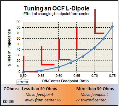
Figure 3
With an antenna analyzer and the information in Figure 2 and Figure 3, you can impirically tune a Tall (or Wide) L-Antenna as closely to 50 Ohms as possible as follows:
Calculate 1/2 wave wire length: 150/MHz = meters (Example at 6 meters: 150/52.5 = 2.857m)
A velocity factor depending on metal, wire size and coating helps... but is not really needed.
Calculate trial long arm bend point: meters * 0.6 = meters (Example: 2.857 * 0.6 = 1.714m)
The long arm goes up for a Tall L-antenna. (The long arm goes to the side for a Wide L-Antenna).
Adjust the side arm for lowest SWR at target frequency. This is the correct length. You now need to find the ratio that gives the best SWR match. A telescoping ends are very handy for tuning.
According to the quidance in Figure 3 or the calculations below, repeat tuning until satisfactory.
Rule 1: If the impedance is low, the ratio is low. The side arm is short - Increase the ratio.
- Example: guestimate 0.62 ratio. Recalculate: 2.857 * 0.62 = 1.771m and adjust both arms.
- Example: guestimate 0.58 ratio. Recalculate: 2.857 * 0.58 = 1.657m and adjust both arms.
* If the impedance of a
center-fed dipole is around 30, 35 or 40 Ohms, this table provides a
estimate of the Off-Center-Feed ratio that will give approximately 50
Ohms.
|
40 Ohms |
35 Ohms |
30 Ohms |
OCF Ratio
|
|
44 |
38 |
33 |
0.60 |
|
49 |
43 |
37 |
0.65 |
|
58 |
51 |
44 |
0.70 |
|
70 |
61 |
52 |
0.75 |
|
91 |
80 |
68 |
0.80 |
Dick Reid, KK4OBI at QSL.net