
Navigation
Menu
Center-fed Bent-Dipoles
Horizontal Lateral
Vertical
- OCF
Slow-Wave
Other Topics
Home
The antenna characteristics become more vertical.
From the OCF Impedance study it is found that the proper length of #14 wire bent 60% vertically and 40% horizontally gives a 50 Ohm match at 1/2 wavelength high feedpoint. The question is...
What happens when you change the angle
of a 0.6 OCF Tall L-Dipole?
of a 0.6 OCF Tall L-Dipole?
To answer this question a generalized OCF antenna model was developed where where any length of wire could be bent at any point and each arm could be set at any angle. For this study the long arm is fixed vertically and the angle of the shorter side arm is adjusted upwards in 15� increments starting from a vertical OCF dipole. At each angle the optimizer function of the model evaluates the the results for SWR and reactance +/-j, adjusts the length of the wire and repeats the model until the best SWR and reactance values are found.
4NEC2 Antenna Model: Here
Figure 1 summarizes some key results of this 0.6 bend ratio antenna model study.
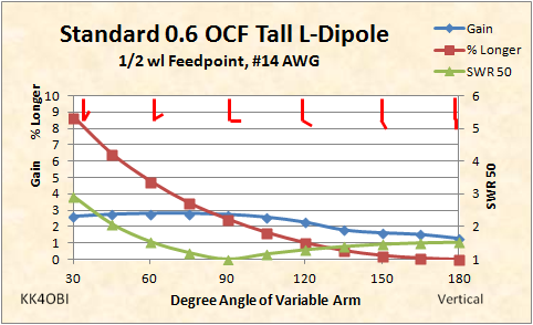
Figure 1
Representations of the angle of bend are shown red..
Read: maximum bend at the left; a vertical dipole is at the right at 180�.
Consider also that the Short arm is toward the ground. Because of this off-centerness the impedance is slightly higher than a center-fed configuration... around 76 Ohms or a SWR 50 about 1.5 : 1. Follow the Green SWR 50 curve from 180� and see it steadily drop to 1:1 SWR at 90�. Beyond that the SWR begins to rise rather rapidly.
When a resonant straight wire is bent it becomes shorter causing the frequency to rise. To maintain the desired tuning the wire must be longer. The red line tells how much % Longer. For example, to stay on frequency at the sweet spot of 90�, the wire must be 2.5% longer than the 180� vertical.
Gain (Blue line) starts at 1.3 dBi for a 0.6 OCF vertical dipole. On Figure 1, follow the line to the left. Gain rises! At 90� to 60� the Gain reaches 2.8 dBi... more than double. How can a vertical with a dinky little side arm radial have gain? To get gain you gotta lose gain somewhere.
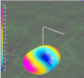
From the Horizontal and Vertical L-dipole studies it is known that the far field radiation pattern around an L-antenna is not round. The change in antenna characteristics are very interesting in the Tall L-dipole form. But before we bend it, let us first take a look at the OCF vertical dipole in Figure 2.
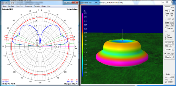
Figure 2
OCF vertical dipole fed 0.4 from bottom.
Compared to a center-fed vertical dipole the thing that pops out is the prominent orange topped dome. There is no dome with a center-fed dipole. Gain is less too. 1.3 dBi versus 1.6 dBi which suggests that the extra 0.3 dBi is directed into the upper lobe at 40-45�. Now lets look at the change in far field radiation pattern when the side arm is bent to 90�, the Tall-L antenna configuration.
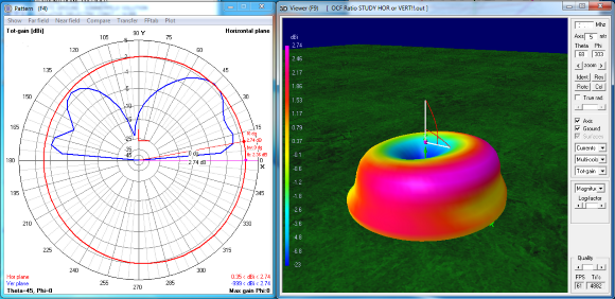
Figure 3
OCF Tall L-dipole, side arm 90�
In Figure 3, the strongest 3D radiation (Purple) is higher and associated with the side arm. This gain is 2.75 dBi at 45� and it extends almost in a semi-circle around the side arm. There still is significant signal (Red) at 10� above horizontal as indicated on the graph (Blue line) and by the red 3D color low to the sides of the horizontal arm. This directional gain will be of help for DX communications. The Front-to-Back ratio is 2.4 dBi which would be heard as a clear difference when you rotate the side arm towards or away from a signal. Note also that it rotates in only 0.2 wavelength radius.
What happens if you raise the side arm above horizontal?
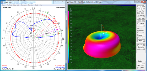
Figure 4
OCF Tall L-dipole, side arm 60�
In Figure 4 the side arm is 30� above horizontal. The gain has increased slightly to 2.81 dBi
and notably (Purple) to the sides of the arm. The low angle radiation remains the same but Front-to-Back ratio slips a bit to 2 dBi.
However, the impedance has passed the 50 Ohm point and is now down to 32 Ohms making the SWR 1.6 to 1... similar to the 180� vertical dipole but with gain because of the side arm.
Staying in the side-arm range of 15� above or below horizontal takes advantage of the non-critical nature of tuning a Tall L-antenna. In that range Gain is highest, around 2.8 dBi. Radiation Efficiency is highest, around 51%. Front-to-Back ratio is best at about 2.4 dBi. SWR is 1:1 +/- 0.1 dBi.
Wherever the Tall L-Antenna is mounted, tuning is relatively easy by adjusting the length and angle of the side arm. In one sense it performs better than a vertical because of the gain towards the arm. In polarity QSB DX situations it hears better (by A-B switching tests) than a vertical because of the horizontal arm. Likewise it is good for local QSO's between vertical antennas and horizontal antennas.
If an identical second side arm is added at 180� opposite, the directional pattern dissapears and becomes only slightly oval. Tuning is needed. The total length will be about 9% shorter, the ratio about 70-30. The commercial version for 10-meters is the MFJ-1790. The Buddipole Versatee option also offers this configuration for Omni-directional vertical operation.
Three identical right-angle side arms at 120� spacing, (75-25 ratio) or, most commonly, four at 90� spacing (80-20 ratio) will make a round radiation pattern. If the side arms are not RF identical, any missbalance from nearby objects will cause the RF current to concentrate away from the non-resonant area which again skews the pattern... the basic problem with elevated radials.
Dick Reid, KK4OBI at QSL.net