 CW RECEIVER FOR 80 AND 40 METERS
The easy 80 and 40 meter Simplest Ham Receiver described on this site
has proven to be (after 2 decades!) versatile, stable, durable and effective. However,
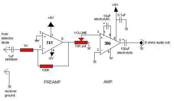
interest and curiosity has been expressed for a version with an audio amp section using integrated
circuits instead of transistors.
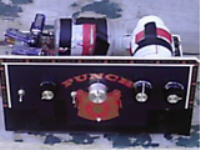
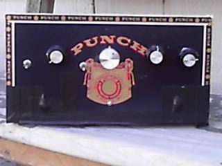
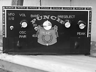
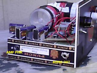
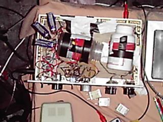
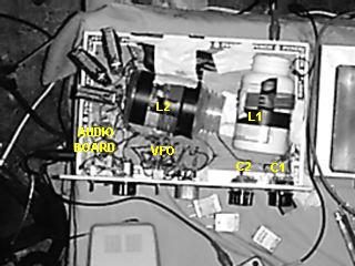
 Instead of just substituting these modifications on my existing Simplest Ham Receiver, an entirely new version was built using a cigar box.
The cigar-box version has all parts very close
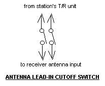
together and no metal panel for the VFO section. When using headphones with my station's setup, and
when transmitting more than about a watt, the antenna lead-in line to the receiver requires an external
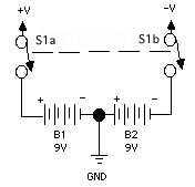
cutoff switch to prevent gross overloading; back-to-back diodes do not suffice (diagram at right). However, when used
with transmitters running about a watt or less, the signal can be monitored comfortably without
use of a cutoff switch as long as the volume is turned all the way down. When using a
simple external audio amplifier and speaker no cutoff switch is needed.
Instead of just substituting these modifications on my existing Simplest Ham Receiver, an entirely new version was built using a cigar box.
The cigar-box version has all parts very close
together and no metal panel for the VFO section. When using headphones with my station's setup, and
when transmitting more than about a watt, the antenna lead-in line to the receiver requires an external
cutoff switch to prevent gross overloading; back-to-back diodes do not suffice (diagram at right). However, when used
with transmitters running about a watt or less, the signal can be monitored comfortably without
use of a cutoff switch as long as the volume is turned all the way down. When using a
simple external audio amplifier and speaker no cutoff switch is needed.
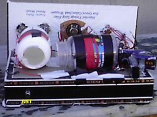
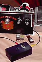 In photo at left, a cutoff switch is housed in a plastic box.
The cables that connect the box from the T/R device to the receiver are common ones left over
from a DVD player. The cutoff switch is not needed at this station when
a simple audio amp and speaker is used instead of headphones. This simple addition makes the operation
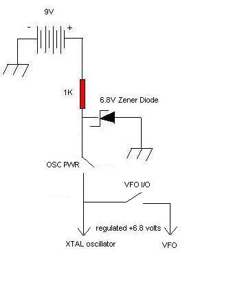
of the receiver much easier and more pleasant. Oscillator crystals also are shown, including
one inserted in a crystal holder: the crystal oscillator is located under the chassis.
In photo at left, a cutoff switch is housed in a plastic box.
The cables that connect the box from the T/R device to the receiver are common ones left over
from a DVD player. The cutoff switch is not needed at this station when
a simple audio amp and speaker is used instead of headphones. This simple addition makes the operation
of the receiver much easier and more pleasant. Oscillator crystals also are shown, including
one inserted in a crystal holder: the crystal oscillator is located under the chassis.
Less than $50 was spent on this project, but lot of parts were on-hand. If everything was purchased the total might come to over $75, which isn't bad for a 2-band receiver capable of receiving more bands if used with converters.