AUDIO Q-MULTIPLIER
Cost estimate: $15
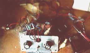
Another wonderful presentation by Larry Lisle, this device greatly increases the ability to separate Morse Code signals by enhancing a particular audio frequency while attenuating the others.
How it Works: The audio output signal of a receiver incoming through T1 is enhanced by a 741 op-amp configured as a Wein-Bridge Oscillator. Variable potentiomenter R1 controls frequency and selectivity/gain is determined by R2. As the gain is increased, selectivity gets better and better because only a signal of the frequency selected by R1 can be transmitted completely around a feedback loop via R4. The signal is then monitored at the output end of T2. A very useful circuit, it is a variable audio frequency generator which produces an almost perfect sine wave and can be used for numerous other projects.
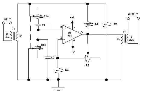 Construction: (Note: if using with the receiver described on this site, the output transformer of the receiver and the input transformer of this project can be omitted; then the output from the final stage of the receiver can be DIRECTLY connected to this input of this project. Therefore, only one transformer is needed for both. To do this, just take out the original transformer of the receiver and insert it as the the output of this project.)
Layout and parts placement are not critical, and once again Fahnstock clips can be used to make all connections except for the lead-in wiring to U1. Highly recommended is the use of a 8-pin IC socket for U1 soldered to a small circuit board - sockets are a good idea whenever using ICs - if something does go awry the IC can just be popped out and replaced.
Construction: (Note: if using with the receiver described on this site, the output transformer of the receiver and the input transformer of this project can be omitted; then the output from the final stage of the receiver can be DIRECTLY connected to this input of this project. Therefore, only one transformer is needed for both. To do this, just take out the original transformer of the receiver and insert it as the the output of this project.)
Layout and parts placement are not critical, and once again Fahnstock clips can be used to make all connections except for the lead-in wiring to U1. Highly recommended is the use of a 8-pin IC socket for U1 soldered to a small circuit board - sockets are a good idea whenever using ICs - if something does go awry the IC can just be popped out and replaced.
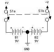 Powering and Operation: in this project the 741 IC uses double-polarity input. Use two fresh 9-Volt batteries and a double-pole switch (any kind, even a knife switch!) as shown above. Attach output of receiver to the 8-ohm (input) leads of T1 (see Note above) and headphones to the 8-ohm (output) leads of T2. Turn everything on, and when a code signal is heard adjust R1 and R2. Experience will teach how the unit works, and switching it on and off while listening will demonstrate how this circuit enhances reception for "solid copy!"
PARTS LIST
Resistors
(all fixed resistors are 1/4-watt, 5% units)
R1 - Dual 100,000-ohm potentiometers
R2 - 100,000-ohm potentiometer
R3 - 15,000-ohm
R4 - 2,200-ohm
R5 - 100,000-ohm
Additional Parts & Materials
U1 - 741 op-amp integrated circuit
     (plus 8-pin IC socket for above)
B1,B2 - 9-volt transistor-radio batteries
T1,T2 - 1,000-ohm to 8-ohm transformers (may be optional; see Note in text above)
C1,C2 - 0.0056 uF, 15-WVDC polystyrene capacitors
                     (other stable kinds OK, and values can be
                      a little different, but use EQUAL value for both;
                      avoid ceramic-disc caps here)
S1 - Double-Pole, Single-Throw Switch (or use 1/2 of DPDT switch...)
Fahnstock clips, screws, knobs, etc.
..need parts?...
Source:
Lisle, Larry, "The Audio Q Multiplier"
                    (Popular Electronics, Vol.6, No.5, May 1989, pp.48 & 110
***HOME***