 2-BAND VFO
-- it uses the same power supply as the receiver (6-8V);
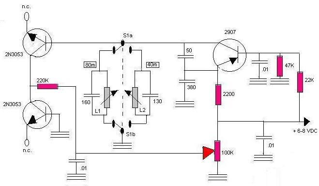
-- it demonstrates use of bipolar transistors as varactor diodes, which enables a simple cheap potentiometer to be used for tuning instead of a hard-to-find and probably expensive variable capacitor;
-- frequency range is easily changed by merely adjusting slugs on coils; and
-- it's buildable and it works.
Decimal capacitance values are in microfarads (uF); whole-number values are in picofarads (pF or uuF).Most general-purpose transistors will probably work in this circuit instead of those shown; back-to-back diodes can of course be tried instead of the 2N3053's.
L1: 4.6-8.5 uH adjustable RF coil. [approximate value-range OK to use]
L2: 2.4-4.1 uH adjustable RF coil. [approximate value-range OK to use]
L1 and L2 available from Circuit Specialists. See Parts Suppliers.
S1: DPDT miniature toggle switch.
Construction and Operation: First breadboard the circuit on a prototyping board (available at Radio Shack and other sources) to make sure it functions properly before soldering. Place the breadboarded (unsoldered) VFO in close physical proximity to the receiver, turn on the receiver, attach a mid-band-of-interest 80-meter crystal to the receiver's oscillator and tune the receiver to 80 meters. Apply power to the VFO and adjust its 80-meter coil slug until a loud signal is heard. Adjust slug to zero-beat the signal when the VFO's tuning pot is at mid-position . Make sure the VFO's switch is set for the right band! Check the VFO's tuning range by using crystal frequencies at either side of mid-band in the receiver's oscillator section. The range should be about 50 kHz.
Repeat calibration procedure for the 40-meter band.
Note: the function of the receiver's tuning cap is actually that of a "preselect" that gets the receiver in the right band for the VFO's tuning function, as well as for the crystal oscillator's function as a "fixed-frequency" tuning device.
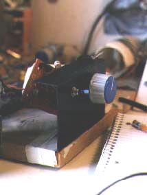
When the breadboarded VFO is working on both bands, go ahead and solder it together on a circuit board. I used a Radio Shack experimenter's board that matches the prototyping board. Other construction techniques such as "dead bug" can be used. To minimize noise and avoid overloading, mount the switch and potentiometer on a small grounded metal panel (half an aluminum chassis box serves well) so that the VFO's circuit board is close to this panel. Do NOT enclose the VFO - leave it exposed! Like the receiver's crystal oscillator, the VFO signal output is not physically wired to the receiver; merely position the VFO as close to the receiver's L2 as you can. Be sure you have easy access to the switch, tuning pot, and (if you are using one) the Audio Q-Multiplier control knobs. Don't remove the receiver's crystal oscillator - it comes in VERY handy as a calibration source for adjusting and changing the VFO's frequency and can still function as the receiver's "emergency" tuning section.
That's it - behold tuning freedom!
Source:
American Radio Relay League,
   "Bipolar transistors serve a varactor tuning diodes..." (schematic diagram),
      THE ARRL HANDBOOK, 70th edition, (Newington, 1993) p.4-28