 15 METER CONVERTER
WITH RF AMPLIFIER
Cost estimate: $50
Adapted from part of a homebrew communications receiver by W7ZOI and K5IRK that first appeared in November 1981's QST , this very effective crystal
converter amplifies and "downverts" 15-meter signals which can then be monitored with any receiver capable of tuning 80 meters.
This project is well worth the effort to build: using this converter connected to my Q-Multiplier- and VFO- enhanced Simplest Ham Receiver with a 80/40-meter dipole antenna only 12ft up,
at sunspot minimum I have received sporadic-E propogated 15-meter CW signals from Florida, Georgia,
North and South Carolina, Kentucky and Argentina averaging RST 579 from my location in Arizona;
at around sunspot maximum I have had many enjoyable QSOs.
The builder is assumed to have had some electronic project construction experience.
Check the suppliers section for sources of parts.
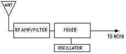 How It Works: 15-meter signals received via the antenna are cleaned up and amplified by the RF AMP/FILTER section. The amplified signal is mixed in the MIXER section with a crystal-generated frequency from the OSCILLATOR section. The mixed ("downverted") frequency is an 80-meter signal sent to the receiver's antenna input.
For example, if a receiver can tune the entire 80 meter band from 3.5-4.0 MHz, the crystal chosen for the converter is 17.500 MHz; with that crystal installed 21.000 downverts to 3.5 and 21.450 to 3.95 MHz. The entire 15 meter band is now available on the receiver.
For receivers with a limited 80-meter range of tuning, an appropriate crystal for the converter can be selected for 80 and 15 meter sub-bands of interest by the same simple math.
How It Works: 15-meter signals received via the antenna are cleaned up and amplified by the RF AMP/FILTER section. The amplified signal is mixed in the MIXER section with a crystal-generated frequency from the OSCILLATOR section. The mixed ("downverted") frequency is an 80-meter signal sent to the receiver's antenna input.
For example, if a receiver can tune the entire 80 meter band from 3.5-4.0 MHz, the crystal chosen for the converter is 17.500 MHz; with that crystal installed 21.000 downverts to 3.5 and 21.450 to 3.95 MHz. The entire 15 meter band is now available on the receiver.
For receivers with a limited 80-meter range of tuning, an appropriate crystal for the converter can be selected for 80 and 15 meter sub-bands of interest by the same simple math.
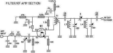
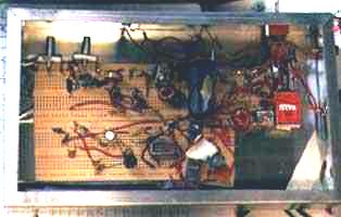
Construction: Construction is not terribly difficult; despite my admittedly sloppy and awkward building methods the converter worked perfectly the first time it was hooked up. For maximum simplicity the project is broken down into three circuit board sections that are connected at completion. The variable capacitors are mica trimmer types except for the 3pF variable in the filter/RF Amp Section - that's a miniature air variable.
Unless otherwise noted, decimal capacitance values are in microfarads (uF)
and whole-number values are in picofarads (pF or uuF).
s.m.=silver mica.
L1, L3, L4 - 10 turns #22 on Amidon T50-6 core.
L2 - 20 turns #22 on Amidon T50-6 core.
Q1 - Dual-gate MOSFET (NTE222, 40673, 2N211, 2N204, 3SK40, or equivalent).
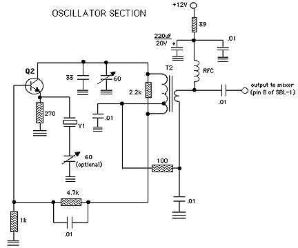
Q2 - 2N3904, 2N2222A or similar general-purpose NPN transistor.
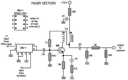
Q3 - 2N3866, 2SC1252, 2SC1365, 2N5109 or similar T0-39 CATV NPN bipolar transistor (Ft=1GHz or better). Use a small heat sink.
RFC - 20 turns #28 enamelled on Amidon FT37-43 core.
SBL-1 - Mini Circuits Lab doubly balanced mixer, or equivalent (Type SRA-1 also suitable).
T1 - 20 turns primary, 4 turns secondary on Amidon FT37-43 core (#24 or #26 enamelled).
T2 - 23 turns primary tapped at 5 turns, 4 turns secondary on Amidon T50-6 core (#22 enamelled).
T3 - 10 bifilar turns on Amidon FT37-43 core (#28 enamelled).
Y1 - Crystal selected for desired downverted frequency range - both fundamental or third overtone types will work.
Z1 - FB43-101 ferrite bead on lead of Q1.
Misc. - Chassis box, crystal socket or holder of some kind, hookup wire, solder, etc.
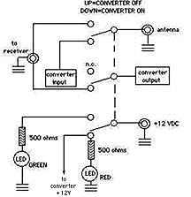
Shown below is a simple, useful and attractive optional circuit for switching the converter in and out of the receiving system without having to change antenna cables and power supply feeds. The red LED lights when the converter is on; the green LED confirms that power is available for the converter although it is switched off.
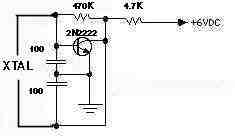 Tuneup: Position a 15-meter transmitter with dummy load attached or an oscillator that will work on 15-meters close to a receiver's antenna or tranmission line (a simple oscillator that will work is shown at right). Tune the receiver to the anticipated downverted frequency. Attach the converter to the receiver and power it up. Adjust the 60pF cap in the oscillator section (that connects to T2) for maximum output (loudest tone). If you included the optional variable cap in series with the crystal, go ahead and tweak it to the precise receiver frequency setting desired. Now adjust the three variable capacitors in the filter/RF amp section for loudest tone and optimum bandwidth. Tuneup is now complete; the 15-meter band is yours for exploration!
Source:
American Radio Relay League
     "A High-Performance Communications Receiver"
     ARRL HANDBOOK, 1993 ed.(Newington, CT) pp.30-9 thru 30-13
***HOME***