 |
AMSAT OSCAR-40 Operations
|
||||||||||||||||||||||
| Analogue
Operations Digital Operations AO-40 Hardware EA4LE
/ KC2HAX AO-40 Equipment
AO-40
Links JAMSAT, Scope Experiment
Favorite Personal Pages AMSAT Homepages
|
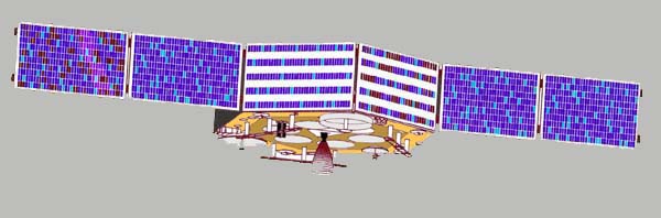
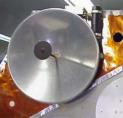
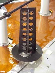
US1/2 Transponder Reception Spacecraft Antennas and Transmitters
AO-40 S Band antennas S1 (left) and S2 (right)
Table. Comparison of the theoretical performance of the S1 and S2 transponder downlink, with the satellite in the same position in space and same transponder load. Based on this comparison signals should be at least 6.3 dB (more than 2 S units) stronger on S1. Visit my AO-40 Transmitter antennas page for more details on the S Band (S2) and K Band antennas CW Tests
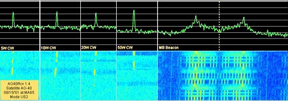
Figure. Uplink test from KC2HAX, CW carriers were transmitted in the U band uplink at different power levels from 5 to 50 watts and received on the S2 downlink, chart shows received signal levels compared with the MB Beacon, each division in the chart is ~10dB
Mode US1 signals from AO-40 on the first day of AO-40 Transponder S1 pass-band operation (August, 03, 2001)
Ground Station equipment (S Band) Modified TSI 3733 Receive converter (~1.1 dB NF, 37 db conversion gain) with own dipole at the focus of a Connifer grid dish (~21 dBi), IF receiver is Yaesu FT-847. Transmitting equipment (U Band) Yaesu FT-847(20 Watts), 11 elements linear polarized Yagi antenna (13.2 dBd) EIRP ~240 Watts
Mode US2 signals from S2 transponder at apogee (60000 Km range) before the raise of perigee.
Ground Station equipment (S Band) Stock TSI 3733 Receive converter (~4.0 dB NF, 37 db conversion gain) with own dipole at the focus of a Connifer grid dish (~21 dBi), IF receiver is Yaesu FT-847. Transmitting equipment (U Band) Yaesu FT-847(50 Watts), 11 elements linear polarized Yagi antenna (13.2 dBd) EIRP ~600 Watts
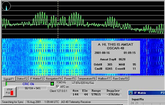
Telemetry Reception
Figure. MB Beacon signal on S2 transmitter received at KC2HAX from AO-40 at 57,816 Km range
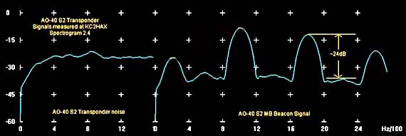
Figure. MB Signal on S2, Chart shows signal to noise ratios as received at KC2HAX, unloaded transponder passband (left) and MB Beacon on S2 downlink (right).
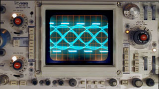
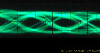
RUDAK
G3RUH 9600bps modem loopback "EYE" Pattern (overdeviated to show EYE details) and RX clock waveform (left). AO-40 RUDAK-A S2 "EYE" pattern received with same modem at KC2HAX (right) RUDAK reception performance to date has been outstanding at KC2HAX. On August 08, 2001 at the time the RUDAK team was downloading the first space images form the SCOPE experiment, the signals were here very strong. With RUDAK on the S2 transmitter (no transponder, no MB) signal was steady S 7 (36 dB over noise floor of 1 S unit here). At the time the S1 transmitter was switched on for RUDAK the engineering beacon (EB) was also on (2400.6 MHz), with this configuration the S-meter showed S9+20. These observations are consistent with more than 6dB gain in signal power as the squint was not yet significantly better. Minutes later the EB was switched off and the RUDAK signal went-up to S9+40dB and peaking at +60 dB !!!!!!! The efficiency meter in WiSP MSPE during the downloading session was showing 100% most of the time.
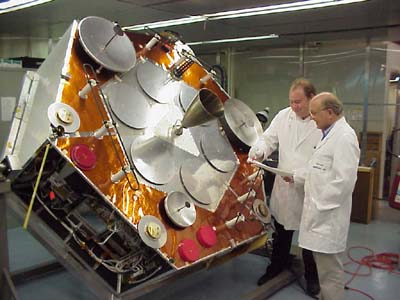
AO-40 at the time it was Phase 3D, Peter Guelzow, DB2OS and Karl Meinzer, DJ4ZC |
||||||||||||||||||||||