The Wheat Box Revealed
 Overview
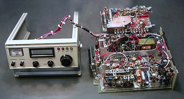
- Allow me to explain the mess you see before you. The board visible in the upper right is the receiver board. It is mounted with four screws, component side down, over the center partition of the main chassis. It can be swung to one side for servicing, as shown in the picture.
- The chassis slides into the main cabinet from the rear along grooves cut into the side panels
- Of course, this rig is built using the "Ugly Construction" method for the RF circuitry
Receiver Board
- The receiver board contains the RX mixer, post mixer amplifier, two Collins mechanical filters, the 455 KHz IF amplifier, envelope detector, AGC, and T/R control circuitry.
- When the receiver board is mounted, all of its adjustments are accessible from the edges. These adjustments are S-meter zero and full scale, AGC bias set point, and the 455KHz IF transformers.
Top Partition (L→R)
- Pilot lamp for S/RF meter
- Behind the lamp is a small Vector board with the RIT control circuitry. This board also contains the end point frequency adjustments for the VTO, which are accessible from the left side of the transceiver.
- 20V, 12V and 5V volt regulators
- AF power amplifier
- Rectifier/filter area
- Power transformer
- The rear panel has a small cooling fan to bring cool air into the cabinet
Center Partition (L→R)
- The frequency display unit
- The transmitter board containing the crystal controlled carrier oscillator, VTO, transmit mixer, buffers, and filters. The last stage is a "high level" drain modulated FET providing about 50MW of real AM drive to the linear output amplifier located in the bottom partition.
- Behind the TX board on the rear panel are connectors for a speaker, microphone, amplifier control and antenna
Bottom Partition (L→R)
- There are two parallel boards in front
- The bottom one contains the three resonator filter and receiver RF amplifier stage
- The upper one is the seven resonator elliptical filter. Yup, I know there are eight cans on this board. I needed two to get the desired inductance value for one of the resonators.
- The speech amplifier and modulator
- MRF148 linear power amplifier
- Antenna changeover & external amplifier control relay
- Low pass harmonic filter
- Rear panel
- Coaxial antenna connector
- Small vent just above PA for pressurized warm air to escape
Front Panel
- The control cable carries two shielded cables connected to the AF GAIN pot
- All other connections to the front panel are DC voltages
- The main tuning control is a ten-turn potentiometer
Back to 75m AM Transceiver Page
Back to Ham Radio Page
Return to George's Place
 ☚
Let's talk about Homebrew Radios!
☚
Let's talk about Homebrew Radios!