About The 40m Transmitter
- The 40m receiver was complete and it wasn't long before the old girl was beginning to look forlorn. It was obvious she needed a mate. Hmmm... Perhaps something tall, dark, and handsome? No, that won't work. She needed something short, wide, and solid state.
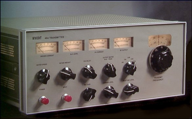
- This transmitter can operate on the 40m band without time limit at an output power level of 100W into 50Ω on CW and RTTY, 100W PEP on SSB, and 25W carrier on AM (100W PEP with 100% modulation). The final amplifier stage runs a pair of Motorola MRF150 high-voltage RF power TMOS-FETs in push-pull configuration, biased for class AB linear operation. Although the PA stage is capable of substantially more power, limiting the output to this level is an act of kindness to a pair of expensive transistors and provides a standard output level for driving most legal-limit amplifiers.
Some Highlights
- Modes of operation − CW AM USB LSB FSK
- Dedicated connector on back panel for a packet TNC
- An electronic keyer based on the ubiquitous Curtiss 8044AB iambic CW keyer chip
- Front panel controls for these CW functions:
- Keyer speed
- Keyer weight
- Break-in hang time
- Sidetone level
- Metering (L → R)
- Driver current − 250mA full scale
- ALC level
- PA Current − 10A full scale
- RF output meter which can be operated in peak or average mode
- Low-level generated AM signal bypasses the narrow SSB filters for full fidelity
- Front panel controls for mic gain and carrier level
- Rear panel connections for RX muting and amplifier control
- Internal DC power supplies permit 120 VAC line operation
Technical Information
Back to Ham Radio Page
Return to George's Place
 ☚
Let's talk about Homebrew Radios!
☚
Let's talk about Homebrew Radios!