EPROM
ERASER
TIMER (3-55')
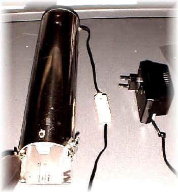
After
building the eprom eraser it was difficult for me to remember to switch-off it
after the necessary time and because a long erase can damage the eprom, I
decided to make a timer.
But I needed an easy, very small timer for a time of 5-30 minutes;
As you can see on schematic a NE555 is used as a square wave generator (clock)
for a CD4040 (frequency divider);
the output of CD4040 drives a transistor wich switch ON/OFF a rele';
at the end of the CD4040's cycle the transistor switch off the rele';.
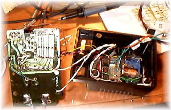
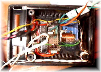
Schematics
is very simple: the difficult is to put all in a small black-box;
pushing down the button activate the timer;
you can change the time changing the NE555 RC network (R1,VR1,C1) or the CD4040
output pin;
I've used a variable resistor on the backside of the box to change the time as I
need;
a red led indicate if the timer is ON/OFF.
If you want you can avoid using NE555 as clock generator and use the frequency of the supply line (50-60Hz if you use a diode,100-120 Hz if you use a bridge) to drive a CD4020.
Components
R1=2K7
R2=1M
R3=6K8
R4=12K
VR1=5-500K
C1=2MF poly
C2=10NF
C3=100NF
C4=100NF
C5=470MF electrolytic
C6=100NF
D1=1N4148
RL1=RELE 2 V- 2 SC
TR1=PNP BC327
IC1=NE555
IC2=CD4040
P1=PUSHING BUTTON
RED LED + 1k resistor
73 de iz7ath, Talino