IC8POF's "secret way" of How_To access into the mk_V Field rig
and work on the RF_board.
IC8POF's "secret way" of How_To access into the
mk_V Field rig
and work on the RF_board.
It is not an easy
decision to open such an electronic equipment, specially if it is (was...)new.
I have opened the Field rig already ...sometimes ...untill now.
So I already knew that I would need only 2 screwdrivers,the crossed for all the screws
and the stright only for opening the +V connector going into the PSU unit

Specially accessing the RF board, which has to be completely extracted from the rig's chassis
for adding the mods.or eventually for reparations.
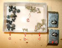
Here are alle the screws to be removed: a= external covers , b= side panel blocking, c= RF-PA&Fan, d= handle, e=RF_board,PSU,FrontPanel
Follow this link for mini_board & switches adding infos.
Going deeper :
Click on the images to have more detailed views.
1) remove the top and bottom covers.
...Pay attention to the bottom cover that retents itself on the chassis.
...Force it with the fingers both sides to pull it down&rear gently.
...No pics for that operation.
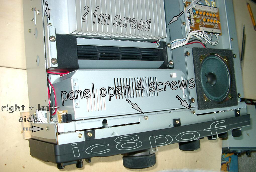
2) remove the cooling fan as shown in the "final-open.gif" picture.
...It is held by 2 screws on the RF_Pa unit and has enough long wires to lay it on the table,
but maybe unplugged for better operation.Write down the plug's position !

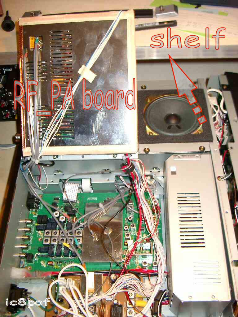
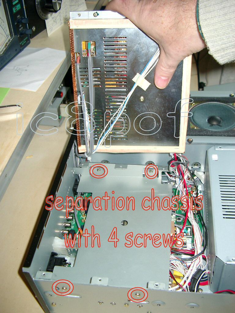
3) To remove the RF_Pa unit Better should be said to rotate it upward and supporting to the rig's console .
...because the RF_PA has not enough long wires to route it outside the rig.
...Or be prepared to tie firmly the unit with a rope if you have not a back shelf.
...pay attention not to let the unit to slip...
...next remove the chassis-separation between the RF_PA and the RF_RX board , very easy to do
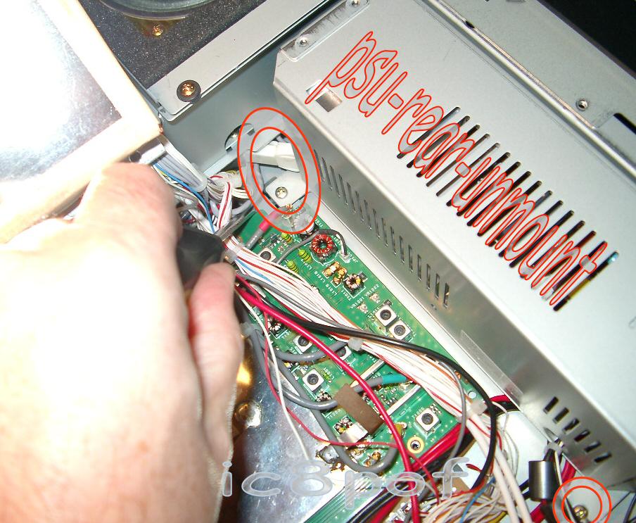
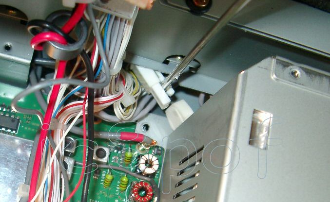
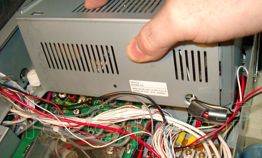
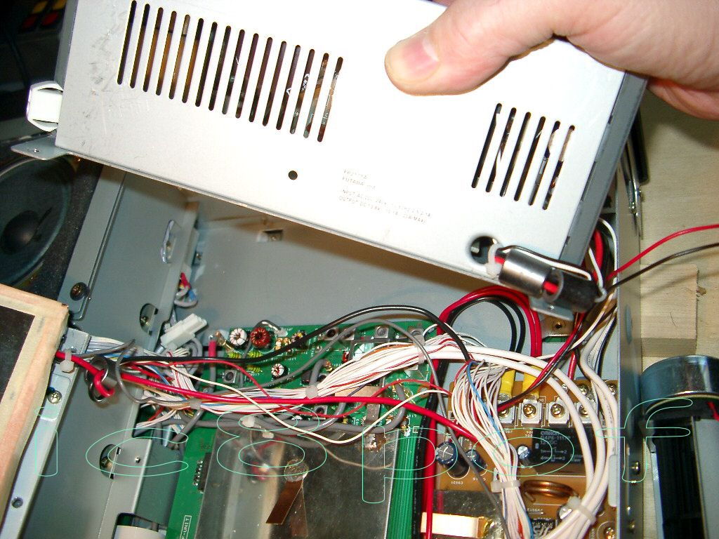
4) Getting out the psu.
2 steps are nedeed : 1) open the Front Panel, 2) removing the Rx_Rf_board shield
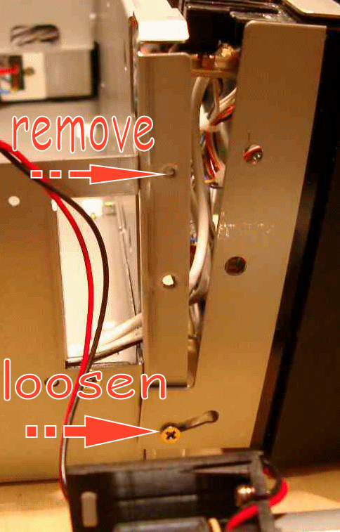
The Front Panel must be opened and rotated a little. It is retained by 6 screws.
2 screws are at the top of the F_P and 4 screws are 2 per side (look at the fan&panel and control-panel pictures),
Not difficult to do, but one must know that.
The 2 screws at the bottom of the sides have to be only losen to get the "FP" rotating a while
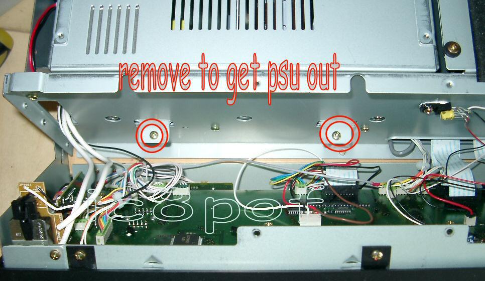
The next step is to remove the RF_board shield :
It is located around the Rx_Rf board,fixed by 3 screws and must be removed to get out the PSU unit.
Care must be taken to pull the rf_shield out because there are many wires running between the RF board and the PSU.
Removing the PSU is now easy but still taking care to the wires.
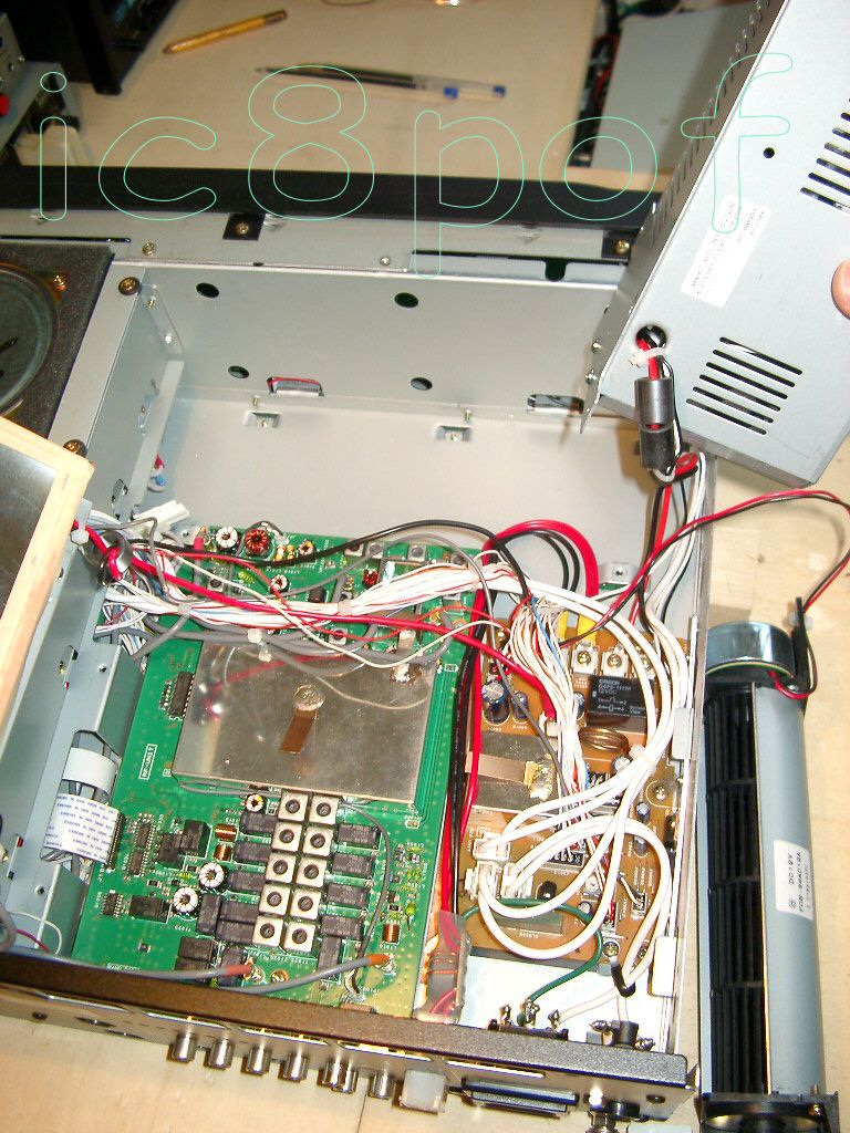
5) Getting out the RF_unit.
...Remove the coax cables by turning&pulling gently the connectors and the flat "control-cable"
...Look again at "Open-Field 1&2" pics.
The RF board must be pulled toward the front panel gently to free the plug-sockets from the rear panel,
then be removed by raising the sockets side up first and tilting a lttle to come out of the wires.
Having the RF board in the hands comes the easier part of the work.
If you want only to add the Anti_Click mod. by W8JI just solder one wire routing it
in the same way as on my picture so your wire will face directly the through hole
in chassis and re_run backward all the steps to close the rig.
PTT Lin switch on\off
If you feel frustrated like me everytime to go on the rig's rear and move that
switch to have lesser noise when not using the Linear Amplifier, then be prepared to add a
mini_connector as the one I had . Be sure to measure the depth between the RF board and the chassis
My connector was just few thousands of inch larger than the available space so had to file it
a little to get the proper depth dimension. you want to add also a duplicate switch for the "Lin PTT" which is located on the rear
of the rig and
|
|
dicembre 2004, febbraio 2007
