Main
Shootout Report Vertical
Shootout Horizontal
Shootout
Feedpoint

CLICK ON
PHOTO
TO ZOOM |
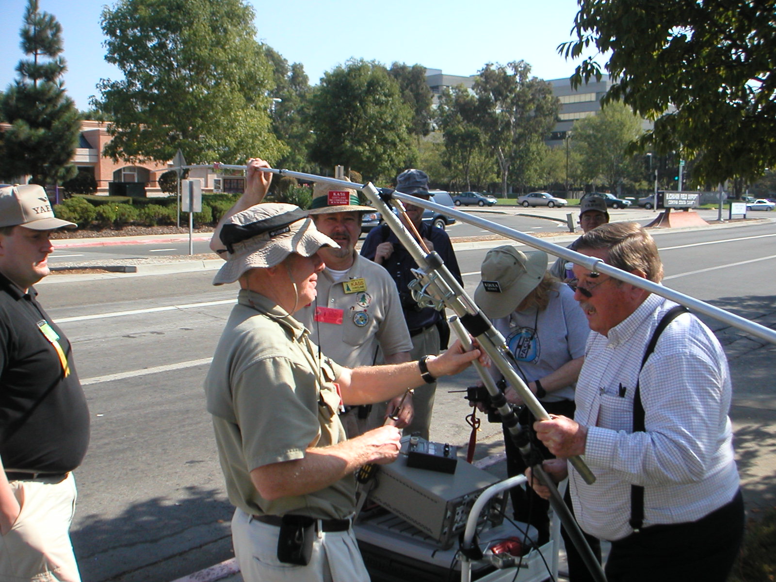
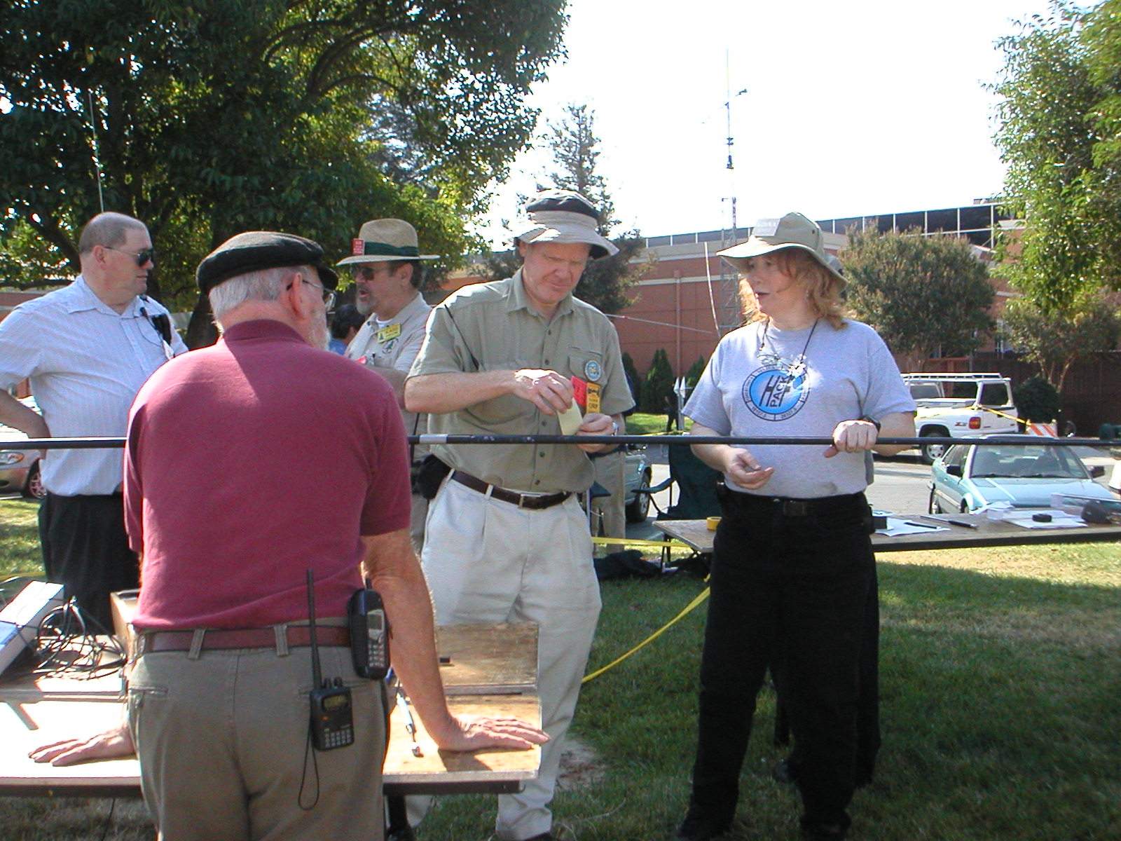
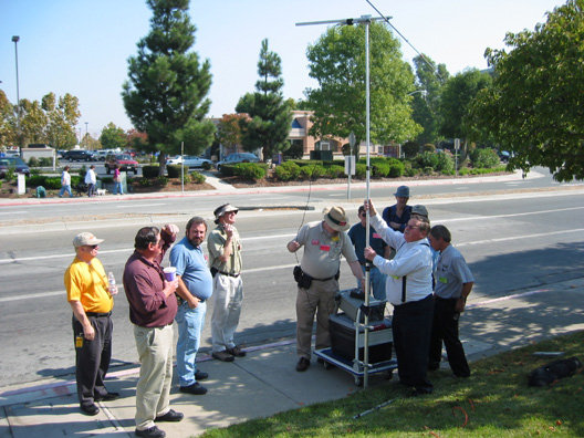
Standard Feedpoint and Support Fixture.
The Standard Feedpoint and Support Fixture consists of an ABS plastic
box mounting flange bracket situated upon a mast at adjustable height.
The Vertical fixture support is a hollow tapered composite fiber telescopic
pole. The Horizontal test support is a telescopic aluminum pole.
The fixture uses a 50 ohm impedance 1:1 balun/unun made from 11 turns
of miniature 50 ohm impedance coaxial cable solenoid-wound upon a ferrite
stick core within a few inches of the antenna feedpoint. 20 feet of RG-58A
coaxial cable connects the Standard Feedpoint Fixture to the Test Transmitter,
with the TX and battery placed upon a table adjacent to the support mast.
The antenna side of the transmission line balun connects via BNC connectors
to interchangeable adaptors for PL-259, SO-239, or 3/8-24 stud terminals
to mate with the various Antennas Under Test. |
Vertical
Reference
Antenna


CLICK ON
PHOTO
TO ZOOM |
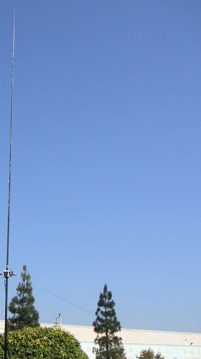
Reference
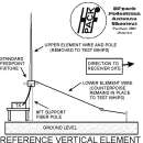
Vertical Element.
 CLICK
ON PHOTO TO ZOOM CLICK
ON PHOTO TO ZOOM
For vertical polarization tests, the Standard Feedpoint Fixture is
set to a height of 8 feet.
The upper element wire, a #14AWG stranded tinned copper wire 16feet
9inches in length is supported vertically upward from the Standard Feedpoint
Fixture by an insulator hollow fiber tapered pole.
The lower element wire, also #14AWG stranded tinned copper wire 16 feet
9 inches in length, is supported from the Standard Feedpoint Fixture, and
this wire slopes down towards the receiver site, ending at a height of
2 feet and supported by nylon cord. The combination of these two
wires forms a dipole-like radiating element with a substantially vertically
polarized wavefront in the direction of the test receiver antenna site.
The lower element wire of the Reference Vertical dipole is maintained
throughout all vertical whip testing as the sole "counterpoise" or "ground
radial" element for the whip antennas to "work against". All Antennas Under
Test utilize the lower element wire as a reference plane or "counterpoise"
unless otherwise noted.
The Reference Vertical Element used for the purpose of this event can
be considered practically to have substantially no positive gain over a
theoretical dipole in free space, and all Antennas Under Test in the shootout
measured in the Vertical Polarization are simply referenced in decibels
with respect to the Reference Vertical Element, with no calibration made
to a theoretical dipole or isotropic radiator in free space. Therefore,
the decibel measurements reported in this chart are advisably utilized
for comparison only among the antennas within each chart itself either
for vertical or horizontal polarization. Due to the unique nature of a
particular antenna range, attempts to draw conclusions of comparison, relative
measurements, or decibel gain/loss claims of other antennas not measured
as part of this shootout with the measurements presented in these charts
may result in significant error due to uncorrelated variables. |
Main
Shootout Report Vertical
Shootout Horizontal
Shootout
HFpack
Reports
HFpack Pedestrian Antenna Shootout 2002
Test Equipment - Accuracy
- Test Sites
|
CLICK ON ANY PHOTO TO ZOOM
Test Receiver

 |
Hewlett Packard spectrum analyzer Model 8591E. Digital readout
measurement in 0.01decibel increments. Center Frequency 14095kHz, 1kHz
resolution bandwidth, 1kHz video bandwidth, 10kHz sweep. Test Transmitter
is keyed, and shortly thereafter, an amplitude measurement is made using
the marker peak function. After the measurement is frozen, Test Transmitter
is unkeyed. A signal from the Reference Element is received in the range
of -20 to 0dBm, and a noise floor of lower than -75dBm within the measurement
band is noted. Power for the analyzer is supplied by 110VAC mains / portable
generator.
CLICK ON PHOTO TO ZOOM |
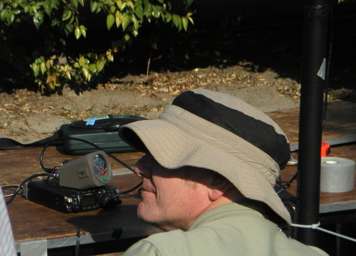
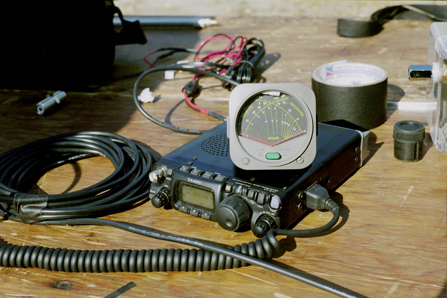
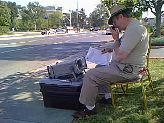
Test Transmitter
 
CLICK ON PHOTO TO ZOOM |
Yaesu FT-817 transceiver, 4 Watts output on 14095kHz CW, powered by
an external 12V gel battery pack, isolated and insulated, placed on a wooden
table adjacent to the support mast for the Antenna Under Test. The RF output
of the transceiver is fed to a Diamond dual-needle power meter, which monitors
forward and reflected power, is used with a 20 feet long RG-58A coaxial
cable connected to the BNC connector of the Standard Feedpoint Fixture
balun/unun. Excess length coaxial cable is coiled adjacent to the transceiver
and secured with gaffers tape. |
Vertical Shootout
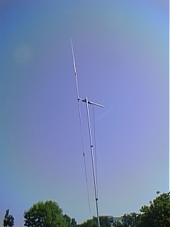
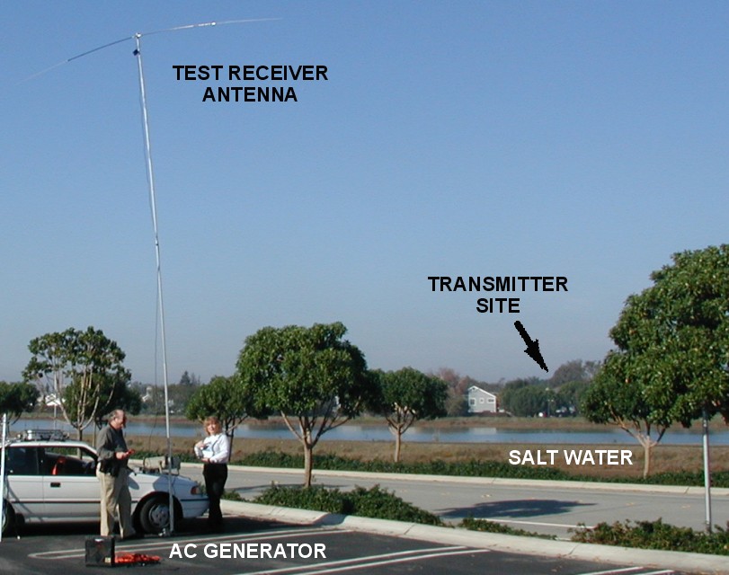
Test Receiver Antenna

CLICK ON PHOTO TO ZOOM |
Dipole consisting of a SuperAntennas
model YP-1(driven element of YP-2) with 20meter loading coils, and
1:1 balun at the feedpoint. Supported by a segmented pole adjacent to the
Test Receiver at a feedpoint height of approximately 20 feet at the feedpoint.
Dipole is physically oriented as a vertical dipole for the vertical measurements.
The SuperAntennas Yagi Portable
YP-2 boom keeps the dipole away from the support pole when in vertical
polarization configuration. |
Horizontal Shootout
Test Receiver Antenna
 |
Horizontally polarized dipole consisting of a "Hamstick
dipole", a rigid coil-loaded dipole elevated about 25ft high on a Super
Antennas telescopic tubular aluminum mast, with a Super
Antennas drive-on portable mast mount. Approximately 30ft of RG58 coaxial
cable with a 1:1 balun at the feedpoint. Antenna aimed broadside to the
transmitter site.
CLICK ON ANY PHOTO TO ZOOM |
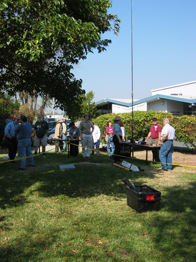
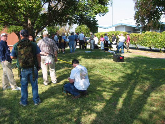
Vertical "Test Range"
Convention Lawn
 
 
CLICK ON PHOTOS TO ZOOM |
Approximately 80 meters distance between Test Receiver Antenna and
Test Transmitter Antenna. Approximately equivalent to 4 wavelengths at
the test frequency 14095kHz. Flat grassy area with some adjacent trees
and other objects. Soil conductivity unknown. Suburban semi-industrial
area. Three nearby wooden flagpoles. Location: at Pacificon
ham convention in Concord California USA. Participants maintained control
of placement of nearby people, adjacent antennas and metallic objects during
tests. Several times, measurements had to be delayed due to passing vehicles
or antennas being accidentally deployed above ground level in the nearby
antenna preparation area. |
Horizontal Test Range:
Salt Marsh
Salt Water
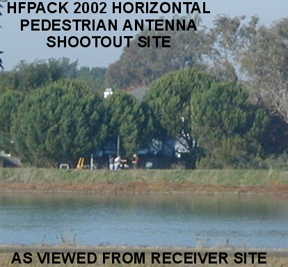
CLICK ON PHOTO TO ZOOM |
Approximately 600 meters distance between Test Receiver Antenna and
Test Transmitter Antenna. Far field range, near zero degree elevation angle.
Transmitter set up on a flat area of low ground cover vegetation and highly
conductive soil, without nearby above-ground conductive objects. An underground
salt water table approximately 1 or 2 meters is below the surface. In addition,
a recent rain provided damp ground, contributing to conductivity. Midway
between the receiver and transmitter, is a body of salt water formed by
a tidal slough at medium-high tide. Receiver set up on an asphalt parking
lot on the opposite shore of the tidal slough. This site, with some of
the most conductive soil in the world, provides a stable measurement environment,
nearly ideal for testing antennas. The location is on the western shore
of San Francisco Bay, California USA. |
Overall Accuracy

CLICK ON PHOTO TO ZOOM
 |
Overall uncertainty of vertical shootout measurements is guestimated
at +/-0.75dB. The overall uncertainty of horizontal shootout measurements
is guestimated at +/- 0.3dB. No specifications or guarantees for overall
accuracy are presented. However, it is believed that all measurements were
performed on an equal and fair basis, and therefore this shootout provides
a worthwhile comparison for determining radiation efficiency at among antennas
in the same class. Minor fluctuations in the vertical test range due to
the presence of people and objects in the vicinity of the shootout may
have contributed to a small degree of fluctuation, but measurements were
taken in a manner which provides some immunity to such random influences,
and careful management of near field objects was maintained. All of the
antennas in the test were tuned to the lowest SWR obtainable at the test
frequency. Some antennas exhibited a 1:1 SWR, while others exhibited a
1.5:1 SWR or less (due to impedance matching at 50ohms). Some antennas
did not present a good match to 50ohms, and efforts were made to tune the
system to resonance by slight variation of counterpoise length. In some
cases, notations are indicated in the report for the antennas which had
matching or tuning problems on a case-by-case basis.
CLICK ON ANY PHOTO TO ZOOM |
Main
Shootout Report Vertical
Shootout Horizontal
Shootout
HFpack
Reports
HFpack Pedestrian Antenna Shootout 2002
People
|
The members of HFpack wish to express their sincere
gratitude and appreciation to everyone who made the HFpack Pedestrian Antenna
Shootout possible.
The following people
volunteered
their time, resources,
and efforts:
-
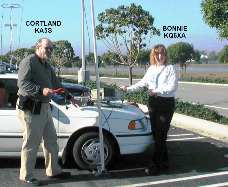
Bonnie KQ6XA (Organizer, Engineer, Equipment Provider, Website, Report)
-
Ken WB6MLC (Registration, Engineer, Staff Organizer, Documentation)
-
Cortland KA5S (Receive Site Engineer, Documentation, Photographer Horizontal)
-
Oliver KB6BA (Transmit Site Engineer, Equipment Provider)
-
Sharyl W3VET (Official Photographer Vertical, Tech)
-
Glenn WB6W (Equipment Provider, Tech)
-
Vern W6MMA (Equipment Provider)
-
Budd W3FF (Organizer)
-
Bill K6ACJ (Photographer)
-
Bil KD6JUI (Photographer)
-
Harry W6DXO (Tech)
-
Chris W6HFP (Tech)
-
Many other HFpackers (Assisted and Witnessed)
|
| Please contact us if you, or anyone you know, should be listed here. |
|
| HFpack especially thanks the volunteer staff of Pacificon! |
|
Main
Shootout Report Vertical
Shootout Horizontal
Shootout
HFpack Reports
HFpack Pedestrian Antenna Shootout 2002
Guidelines
|
The purpose of the HFpack Pedestrian Antenna Shootout is to try out
a variety of pedestrian antennas, measure and document the antennas in
a well-controlled manner, and report the results as
a service to radio operators around the world interested in furthering
the state - of - the - art for HF portable.
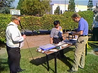
1. All antenna entries should be physically present to register at the
HFpack Shootout site, Pacificon Convention, at 11am on Sunday, 20 October
2002.
2. The antenna shootout is for "Pedestrian Antennas". A pedestrian
antenna is considered to be a lightweight antenna that can easily be carried
to the shootout by one person in a backpack or bag. It is not necessary
to walk around carrying the antenna while in operation. The shootout is
not intended to include heavy antennas designed mainly for base station
operation, thus, antennas exceeding 11 pounds are discouraged from entry.
3. The test transmitter has a feedline with a 1:1 balun/unun at the
feedpoint. The test feedpoint (antenna mounting point) is elevated above
ground level, and provides a BNC, SO-239, or 3/8-24
female threads, or terminal lug to connect the antenna to. The balun
has at least 20dB of isolation at 14MHz.
4. During the RF measurement, the test transmitter delivers about 5
Watts CW into the entry antenna for about 30 seconds.
5. For vertical quarterwave whips, the feedpoint has a single quarterwave
resonant "radial" counterpoise, sloping down at about a 45 degree angle
in the direction of the test receiver site. No other
counterpoise will be used for quarterwave whips.
6. Since the objective is to remove any extraneous variables from the
RF measurement, the standard antenna test fixture will be used for all
antennas. So no other feedline will be used, and it is not necessary
of desirable for the entry antenna to include a support pole, since
the support is provided by the test fixture.
7. Commercial antenna manufacturer personnel may not participate as
part of the HFpack Shootout engineering measurement team, however they
are invited to be present and help set up their antenna on the test fixture.
8. The only frequency of the shootout is 14.1MHz (+/-10kHz).
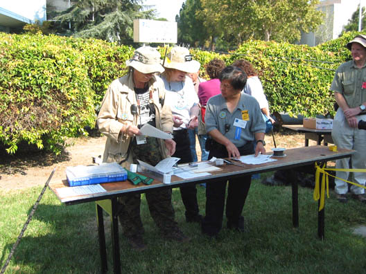
9. Antennas will be physically measured (inches), weighed (pounds),
photographed (digital), and tested for radiated RF on the test range. The
results of the tests, measurements, photographs, and description
of the antenna may appear on the HFpack website or other publications.
10. Antenna RF radiation will be measured by a calibrated test receiver
using linearly polarized small antenna on an elevated support pole. The
test receiver antenna will be operated first in vertical and
then in horizontal polarization. The entry may enter appropriately
in either the horizontal or vertical polarization category.
11. Horizontally polarized antennas and vertical antennas not requiring
a counterpoise will be elevated to 16 feet at the feedpoint or radiation
center.
12. Antennas should self-match to 50 ohms nominal impedance.
13. Antenna owners who are not present may privately arrange for another
person to enter their antenna.
14. A commercial antenna may be entered by anyone who owns it, however,
multiple entries of the same type of commercial antenna by different owners
is discouraged.
15. The general public, amateur radio operators, volunteer witnesses,
and others will be present to view the shootout.
16. Other guidelines may be posted or verbally announced or personally
advised at the shootout.
17. Requests to test an antenna using other than the standard testfixture
and methods will probably be rejected unless there is a good and compelling
techical reason to do so.
18. In the unlikely event of confusion or dispute, a panel of 3 HFpack
members chosen by the HFpack members present at the shootout will attempt
to resolve the issue in an amiable manner.
If you are interested in participating in the next HFpack Pedestrian
Antenna Shootout, please
sign up for HFpack Special Bulletins, on the HFpack
egroup.
Various HFpack events, such as HFpack Technical Forums,
HFpack Rallies, HFpack Pedestrian Eyeball QSOs, HFpack Lunches, and HFpack
Shootouts are held at Dayton Hamvention
and Pacificon Convention in California.
|