Click on a photo
to view full size |
 |
 |
Click on a photo
to view full size |
 |
 |
Click on a photo
to view full size |
 |
 |
Click on a photo
to view full size |
 |
 |
Click on a photo
to view full size |
 |
 |
Click on a photo
to view full size |
 |
 |
Click on a photo
to view full size |
 |
 |
 |
 |
Click on a photo
to view full size |
 |
 |
 |
Click
on a photo
to view full size. |

|
|
|
|
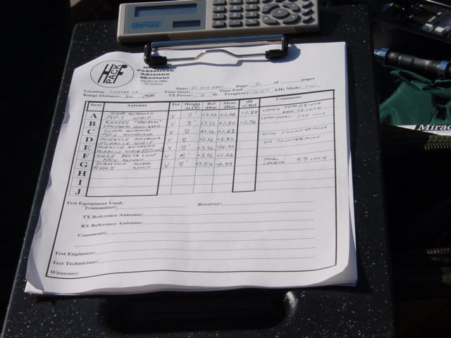
Results of
the
HFpack Pedestrian Antenna Shootout 2001
20 meters
Vertical Polarization
| Antenna |
dB
+/-Ref |
Feed
Point
Height
Feet |
Description |
| Reference
Vertical Element |
0.00 |
8 |
Reference
Vertical Element on Standard Feedpoint and Support
Fixture.*
Total Vertical Element
Length: 16feet 9inch.
[Note#1] |
KA5DVS
"PAC-12M" |
-1.76 |
8 |
Homebrew, multiband center loaded band-tapped
coil collapsible tip-tunable whip. Breaks down to 12 inch sections.
Total Length: 105 inch.
photo
info |
SuperAntennas
MP-1 |
-1.88 |
8 |
Commercial product, sliding sleeve continuously
tunable "manual screwdriver" pedestrian/ portable/ mobile telescopic whip.
Total Length: 68 inch.
info |
KA5DVS
"PAC-12" |
-1.88 |
8 |
Homebrew, single band center coil loaded
tip-tunable collapsible whip. Breaks down to 12 inch sections.
Total Length: 108 inch.
photo |
SuperAntennas
MP-2 |
-1.94 |
8 |
Commercial product, continuously tunable
mini- motorized screwdriver pedestrian/ portable/ mobile telescopic whip.
Total Length: 77 inch.
info |
Webster
Short Bandspanner |
-3.92 |
8 |
Commercial product (not in production),
tip tunable, mobile-style whip. Total Length: 60 inch.
info |
Diamond
Model RHM5 |
-3.95 |
8 |
Commercial product, center coil loaded
band-tapped, tip tunable, pedestrian/ portable/ mobile whip. Total Length:
53 inch.
info |
Waters & Stanton
ATX Walkabout |
-4.61 |
8 |
Commercial product, coil loaded, band-tapped,
tip tunable, pedestrian/ portable telescopic whip. Total Length: 63 inch.
info |
KA5S
Backpack Delta Loop |
-4.82 |
5 |
Homebrew, narrow-angle backpack-mounted,
collapsible, shortened, wire pedestrian/ portable delta loop fed at bottom
apex direct to LDG portable autotuner in pack. Fiber pole spreader Length:
12 feet.[Note#2]
photo |
Outbacker
Tri-Split |
-5.03 |
8 |
Commercial product, coil loaded, band-tapped,
tip tunable, portable/ mobile-style whip. Total Length xx inch.
info |
Outbacker
Joey |
-5.12 |
8 |
Commercial product, coil loaded, band-tapped,
tip tunable, pedestrian/ portable whip. Total Length 48 inch.
info |
Miracle Antenna
Miracle Whip |
-10.48 |
8 |
Commercial product, base loaded tapped-L
network, knob tunable, pedestrian/ portable telescopic whip. Total Length
49 inch.
info |
W6ZO
Portable Delta Loop |
-10.78 |
3 |
Homebrew, wide-angle table-mounted, full-wave,
portable collapsible packable wire delta loop fed at bottom apex directly.
Fiber pole spreader Length: 20 feet. [Note#3]
photo
info |
Miracle Antenna
Miracle Whip
[no counterpoise] |
-29.21 |
8 |
Commercial product, base loaded tapped-L
network, knob tunable, pedestrian/ portable telescopic whip. Tested without
counterpoise connection. Total Length 49 inch. [Note#4]
info |
Results of the
HFpack Pedestrian Antenna Shootout 2001
20 meters
Horizontal Polarization
| Antenna |
dB
+/-Ref |
Feed
Point
Height
Feet |
Description |
| Reference
Horizontal Element |
0.00 |
16 |
Reference Horizontal
Element on Standard Feedpoint and Support Fixture.
Total Horizontal
Element Length: 33feet 6inch. [Note#5] |
W6ZO
Portable Delta Loop |
+1.02 |
3 |
Homebrew, wide-angle table-mounted, full-wave,
portable collapsible packable wire delta loop fed at bottom apex directly.
Fiber pole spreader Length: 20 feet. [Note#3]
photo
info |
W3FF
Buddipole |
-0.77 |
16 |
Homebrew, hand-held pole-mounted, collapsible,
"walking portable" / pedestrian, band changeable coil-loaded, telescopic
tip-tunable dipole. Total Length: 15 feet.
photo
info |
KA5S
Backpack Delta Loop |
-1.47 |
5 |
Homebrew, narrow-angle backpack-mounted,
collapsible, shortened, pedestrian and portable wire delta loop fed at
bottom apex direct to LDG portable autotuner in pack. Fiber pole spreader
Length: 12 feet. [Note#2]
photo |
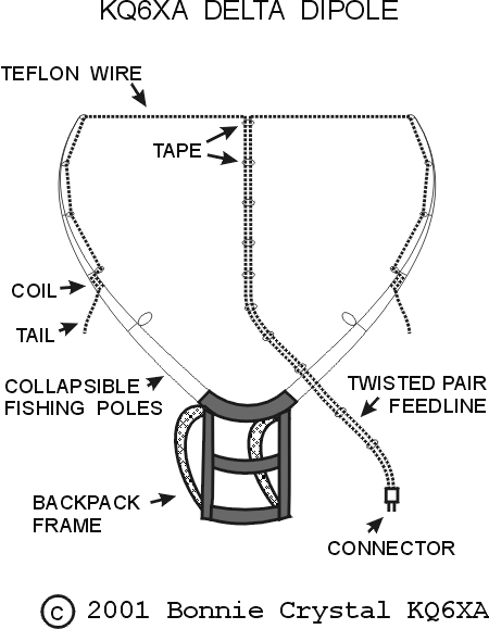
KQ6XA
Delta Dipole |
N/A |
7 |
Homebrew, backpack-mounted, coil-loaded
bent dipole, fed at top center.
Fiber pole spreader Length: 8ft. [Note#6]
info
photo |
Results of the
HFpack Pedestrian Antenna Shootout 2001
20 meters
Notes
| Note* |
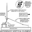
Standard Feedpoint and Support Fixture.
The Standard Feedpoint and Support Fixture,
consists of an insulator box mounting flange bracket situated upon an insulator
hollow tapered fiber mast at adjustable height.
The fixture uses a 50 ohm impedance 1:1
balun/unun made from 11 turns of miniature 50 ohm impedance coaxial cable
solenoid-wound upon a ferrite stick core. 20 feet of RG-58A coaxial cable
connects the Standard Feedpoint Fixture to the Test Transmitter, a
Yaesu FT-817, with external 12VDC Gel Battery, with the TX and battery
housed in an insulated
backpack and placed upon a wooden table adjacent to the support mast.
The antenna side of the transmission line balun connects via BNC connectors
to interchangeable adaptors for PL-259, SO-239, or 3/8-24 stud terminals
to mate with the various Antennas Under Test. |
| Note#1 |
Reference
Vertical Element.
For vertical polarization tests, the Standard
Feedpoint Fixture is set to a height of 8 feet unless noted otherwise.
The upper element wire, a #14AWG stranded
tinned copper wire 16feet 9inches in length is supported vertically upward
from the Standard Feedpoint Fixture by an insulator hollow fiber tapered
pole.
The lower element wire, also #14AWG stranded
tinned copper wire 16 feet 9 inches in length, is supported from the Standard
Feedpoint Fixture, and this wire slopes down towards the receiver site,
ending at a height of 2 feet and supported by nylon cord. The combination
of these two wires forms a dipole-like radiating element with a substantially
vertically polarized wavefront in the direction of the test receiver antenna
site.
The lower element wire of the Reference
Vertical dipole is maintained throughout all vertical whip testing as the
sole "counterpoise" or "ground radial" element for the whip antennas to
"work against". All Antennas Under Test utilize the lower element wire
as a reference plane or "counterpoise" unless otherwise noted.
The Reference Vertical Element used for
the purpose of this event can be considered practically to have substantially
no positive gain over a theoretical dipole in free space, and all Antennas
Under Test in the shootout measured in the Vertical Polarization are simply
referenced in decibels with respect to the Reference Vertical Element,
with no calibration made to a theoretical dipole or isotropic radiator
in free space. Therefore, the decibel measurements reported in this chart
are advisably utilized for comparison only among the antennas within each
chart itself either for vertical or horizontal polarization. Due to the
unique nature of a particular antenna range, attempts to draw conclusions
of comparison, relative measurements, or decibel gain/loss claims of other
antennas not measured as part of this shootout with the measurements presented
in these charts may result in significant error due to uncorrelated variables. |
| Note#2 |
KA5S
Backpack Delta Loop.
This antenna was measured in both the vertical
and horizontal shootouts by request of the entrant. Due to the approximately
3/4wave of wire on 20m and the short loop's narrow vertical angle of the
support spreaders, it exhibits significant vertically polarized radiation,
even though it is fed from the bottom apex. The antenna represents a novel
and viable approach to the problem of pedestrian mobile hands-free operation
by mounting it on a packframe. |
| Note#3 |
W6ZO
Portable Delta Loop.
This antenna was measured in both the vertical
and horizontal shootouts by request of the entrant. However, the antenna
is primarily horizontally polarized. It is the only antenna which showed
positive
gain above the Horizontal Reference Element and a 45dB front-to-side
ratio. Packable and very lightweight when collapsed, it is a huge full-size
fullwave wire antenna which exhibits significant low angle efficiency even
when the feedpoint is mounted very close to ground level, thus requiring
no separate support. The base/feedpoint of the antenna was clamped to the
wooden test table for the shootout testing. The design was not intended
for active use while in motion as a Pedestrian Mobile antenna. |
| Note#4 |
Miracle Antenna Miracle Whip [no counterpoise].
This antenna was measured both "with and
without the counterpoise" by request of the manufacturer. A novel departure
from the more conventional solenoid coil design, this antenna system utilizes
a knob to adjust a tapped
toroidal variable L network for resonating and matching the base of
the telescopic whip. Although measured performance without the counterpoise
was down about 19dB below its performance with the counterpoise, a low
SWR match was easily achieved without the counterpoise connected, while
relying only upon only the stray high impedance coupling across the windings
of the Standard Feedpoint Fixture's 1:1 balun to the
coaxial feedline to provide a reference plane. |
| Note#5 |
Reference Horizontal Element.
For horizontal polarization tests, the
Standard Feedpoint Fixture is set to a height of 16 feet unless noted otherwise.
Two element wires, the same ones used for
the Reference Vertical Element, each made of #14AWG stranded tinned
copper wire 16feet 9inches in length are supported horizontally parallel
to the ground in opposite directions from the Standard Feedpoint Fixture
by insulator hollow fiber tapered poles. Some sag at the ends of the poles
is noticed. The Reference Horizontal Element is rotated and fixed physically
broadside to the direction of the receiving antenna site.
The combination of these two wires forms
a dipole-like radiating element with a total length of 33 feet 6 inches
with a substantially horizontally polarized wavefront in the direction
of the test receiver antenna site.
After reference measurements are made on
the Reference Horizontal Element, it is removed from the fixture. All Antennas
Under Test then utilize the same feedpoint fixture and feedline and are
rotated to the field strength maxima.
The Reference Horizontal Element used for
the purpose of this event can be considered practically to have substantially
no positive gain over a theoretical dipole in free space, and all Antennas
Under Test in the shootout measured in the Horizontal Polarization are
simply referenced in decibels to the Reference Horizontal Element, with
no calibration made to a theoretical dipole or isotropic radiator in free
space. Therefore, the decibel measurements reported in this chart are advisably
utilized for comparison only among the antennas within each chart itself
either for vertical or horizontal polarization. Due to the unique nature
of a particular antenna range, attempts to draw conclusions of comparison,
relative measurements, or decibel gain/loss claims of other antennas not
measured as part of this shootout with the measurements presented in these
charts may result in significant error due to uncorrelated variables. |
| Note#6 |
KQ6XA
Delta Dipole
This antenna was measured, tested favorably
compared to the reference, and independently verified. The decibel results
are not reported because the entrant is an organizer of the event and this
website. Fairness is important. |
|
|
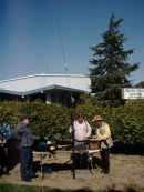
HFpack Pedestrian Antenna Shootout 2001
20 meters
Test
Equipment and Test Range
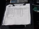
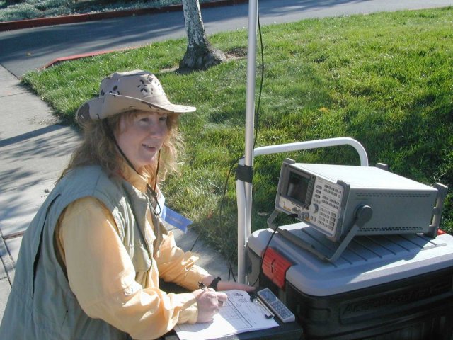
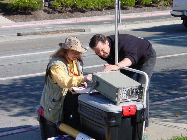
| Test
Receiver |
Hewlett Packard spectrum analyzer Model
8591E. Digital readout measurement in 0.01decibel increments. Center Frequency
14107kHz, 1kHz resolution bandwidth, 1kHz video bandwidth, 10kHz sweep.
Test Transmitter is keyed, then repetitive sweeps are initiated using peak
hold for 15 seconds, then frozen, then marker peak search function is used
to obtain digital readout of measurement. After measurement is frozen,
Test Transmitter is unkeyed. A signal from the Reference Element is received
in the range of -10 to +5dBm, and noise floor of lower than -70dBm within
the measurement band is noted. Power for the analyzer is supplied by 110VAC
mains using approximately 150ft of extension cord along the ground from
an adjacent building. |
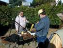
| Test
Transmitter |
Yaesu FT-817 transceiver, 5 Watts output
on 14107kHz CW, powered by an external 12V gel battery pack, isolated and
insulated, packaged and operational in a Communication
Outfitters Expedition Pack backpack placed on a wooden table adjacent
to the support mast for the Antenna Under Test. The BNC output of the transceiver
is used with a 20 feet long RG-58A coaxial cable connected to the BNC connector
of the Standard Feedpoint Fixture balun/unun. Unused coaxial cable is coiled
adjacent to the transceiver and secured with gaffers tape. |
| Test Receiver Antenna |
Loaded dipole consisting of two Pro-Am
20m monoband whips with a 1:1 balun at the feedpoint. Supported by a segmented
pole adjacent to the Test Receiver at a feedpoint height of 16 feet. Insulator
strut utilized to keep lower whip fixed and bent away from support pole
when in vertical polarization
configuration. Polarization changed from vertical to horizontal
by physically moving the dipole bracket 90 degrees on the top of the pole
to orient the antenna. Horizontal azimuth rotation arranged to broadside
with the Test Transmitter site. |
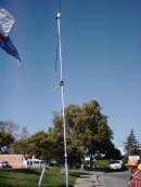
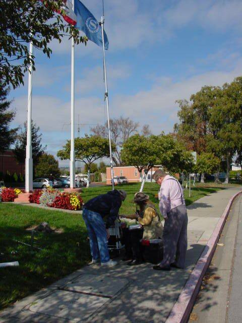
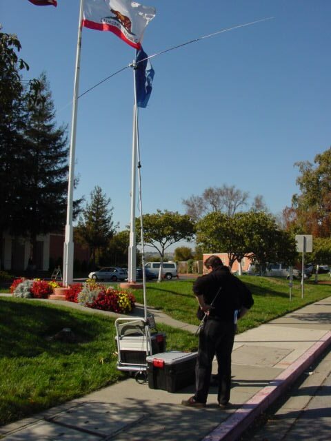
| Test Range |
Approximately 80 meters distance between
Test Receiver Antenna and Test Transmitter Antenna. Approximately equivalent
to 4 wavelengths at the test frequency 14107kHz. Flat grassy area with
some adjacent trees. Soil conductivity unknown. Suburban semi-industrial
area. Three nearby wooden flagpoles. Location: at Pacificon ham convention
in Concord California USA. Participants maintained control of placement
of nearby people, adjacent antennas and metallic objects during tests.
Several times, measurements had to be delayed due to passing vehicles or
antennas being accidentally deployed above ground level in the nearby antenna
preparation area. |
| Overall Accuracy |
Overall uncertainty of measurements is
guestimated at +/-0.3dB (about one-third of a decibel). No specifications
or guarantees for overall accuracy are presented. However, it is believed
that all measurements were performed on an equal and fair basis, and therefore
this shootout provides a worthwhile comparison for determining radiation
efficiency at low elevation angles among antennas in the same class. Minor
fluctuations in the test range due to the presence of people and objects
in the vicinity of the shootout may have contributed to a small degree
of fluctuation, but all measurements were taken over 15 seconds to provide
some immunity to such random influences, and careful management of near
field objects was maintained. All of the antennas in the test were tuned
carefully to the lowest SWR obtainable at the test frequency. Some antennas
exhibited a 1:1 SWR, while others exhibited a 1.5:1 SWR or less (due to
impedance matching at 50ohms). |
HFpack Pedestrian Antenna
Shootout 2001
|


