

GM3WOJ ZL1CT Lattice tower information pages Updated February 2022
DISCLAIMER - failure to install, maintain or use a tower properly could result in serious injury or death, or damage to property. You should make SAFETY your prime consideration when implementing any of the ideas or suggestions given below. I cannot accept any responsibility for any accident or damage which could be construed to result from any advice detailed on this web-page. See the SAFETY NOTES section below.
Update - Aprl 2020 - I have a large amount of extra information, new photos etc. which will be added to these webpages during 2022. I have updated some of the text and checked the links on this page.
These webpages describe how to install, maintain and use a typical base-plate mounted Versatower BP60 lattice tower
Click on these links for information :
(i) Finding the age of your Versatower (Excel worksheet - 36kB - thanks Ian GM3SEK)
* Any extra information you can give us for this Spreadsheet would be much appreciated*
Please e-mail your Versatower serial number and date to gm3sek ...at.. ifwtech.co.uk
(ii) Installation guide for an Altron tower (Adobe PDF - 12.7MB - thanks Neil G3RIR)
Quick links : Versatower (raising/lowering) wiring diagram
Versatower luffing (tilting over) wiring diagram
Fulton K1550 and K2550 winch manuals
Versatower 13M20 Baseplate/post dimensions + photos
October 2008 - Installing towers at the GM7R contest station
In the UK there have been several different manufacturers of lattice steel towers, which can crank-up and/or tilt over. In amateur radio circles, most UK towers are Versatowers, with quite a few Western Electronics towers (Westowers), others made by Altron, Radiostructures or BXI, a few very expensive Luso or WorldWind towers and an occasional American-made tower. Currently (2013) Radio Structures Ltd manufacture lattice towers in Northampton and Upshot UK Ltd manufacture lattice towers in Lymington. If money is no object, WorldWind towers are manufactured in Korea and Luso towers are manufactured in Japan.
It is worth remembering that the top of a '60 foot' (18m) 3-section crank-up tower is actually about 52 feet above ground level, because the sections need to overlap by 3' to 4'. The head unit adds another 4 feet to this height, but you need to extend the stub mast to increase the height to a true 60 feet.
The photos below, and the 2 at the bottom of the page, show the 4 Versatowers here at the GM3WOJ/GM2V contest station in the winter of 2002 and summer of 2003.
1. Identifying the tower
The 'Versatower' ™ is a common crank-up and tilt-over galvanised lattice steel tower, produced originally by Strumech Engineering in the West Midlands. Versatowers were then manufactured by Francis and Lewis International Ltd (FLI) in Gloucester, who ceased production in September 2009. Available heights range from 20' to 120' with mobile, guyed, or free-standing versions, either post, base-plate, socket or wall-mounted and either 'standard' (13M20) or 'heavy-duty' (16M20). The original G3BXI design/business was purchased by Versatower, so BXI towers pre-date Versatowers. In the days of Strumech Engineering, Roy Garbett had been with the company for many years and was very helpful and knowledgeable - thanks Roy.
There are many 50-year old lattice towers still in use, with minimal rust, so it is worth considering firstly the approximate age of the tower.
The link at the top of this page allows you to download an Excel Worksheet (compiled by Ian White GM3SEK - thanks Ian) which correlates Versatower serial numbers with their year of manufacture. Please send more information to Ian if you have a tower with a serial number on the ground post and you know the approximate date of manufacture - we'd like to find the 'oldest known Versatower' ! With the serial number plate being on the ground post rather than on the tower, which might become separated, we cannot guarantee that this information is entirely accurate, but it might be helpful.
Pre-1975 approximately, Versatowers had an system for locking the middle section (nowadays often called the 'catcher plate') which consisted of a long metal rod running up inside one of the legs of the bottom tower section, which moved a metal arm at the top into position below one of the cross-braces of the second tower section - you then lowered the tower back down onto this metal arm. This older system works fairly well, but it is important to keep the top and bottom of this metal rod mechanism well greased. Later Versatowers use a hinged catcher plate at the top of the bottom section, which is moved by a rope running outside the lower section. The October 1970 'Short Wave Magazine' contains an advert (ironically from Western Electronics) for Versatowers as follows : "20', 40', 60' or 85' for £92, £121, £146 or £275. 120' guyed at £380" The October 1979 RSGB 'Radio Communication' magazine contains an advert : "P40 £277, P60 £336, P40HD £416, P60HD £473 (+VAT 15%)" P30 and BP30 Versatowers were also advertised, with 3 x 10' sections and a single winch system. This same advert says "12 years of continuous development..." which implies Versatowers were first sold in 1967. For the first year or so of production, Versatowers were not galvanised. The 'T' series of Versatowers are light-weight. The Versatower 5M20 section is often used to extend a Standard BP80 to 100', but this light-weight top section is only really suitable for small beam or wire antennas.
'Westowers' were manufactured by Western Electronics (UK) Ltd and can be sometimes be identified by the (optional) lattice style of ground-post that they use, which has a sloping top and six bolt holes at the triangular base. Click here to view an October 1976 advert for Westowers (1.1MB .jpg file) Note the comparisons with 'Brand X' and 'Brand Y' - 'Brand X' is probably Versatower - I am uncertain who 'Brand Y' were in 1976. The October 1978 'Radio Communication' magazine contains an advert for Westowers as follows : "1S/P 25ft/7.75m £265, 2S/P 42ft/12.75m £362, 3S/P 58ft/18.75m £431, 4S/P 75ft/22.75m £500" Click here to view information about the Westower range of towers (680kB .pdf file - thanks Gavin GM0GAV) and click here to view a Westower installation/instruction manual (705kB .pdf file - thanks Peter GM8GAX)
 4 of the 6 Versatowers at the (now QRT) GM4NFC DX station in Ayrshire.
2. Where should the tower be installed ?
You need to consider carefully the exact position and orientation of the tower base - here are the key questions :
* Take plenty of time to consider the above issues - you cannot easily move a tower which is installed in the wrong place! *
Positioning your tower so that it tilts over in a North-South direction makes it easy to orientate a yagi and makes the tower a useful polar mount.
3. Installing the Base-plate or Ground-post
Standard and Heavy-duty Versatowers are hinged 6 feet above ground level. Older P120 Versatowers consisted of 3 x 40-foot lattice sections, hinged on a 20-foot high ground-post, with a counterweight. The post-mounted versions e.g. P60, have a 12-feet long square steel ground-post, 6 feet of which is below ground (with flanges at the base) and 6 feet above. The base-plate versions e.g. BP60, have the same top 6 feet of ground-post, but it is welded onto a 3-foot square base plate, which has welded strengthening webs and 4 sleeved holes (spaced 30" centre-to-centre). Note that 'Heavy duty' Versatowers have posts with 6" sides (6BP6) whereas the 'Standard' posts have 5" sides. If you have purchased a tower which does not have a ground-post (quite often they are cut off at ground level, leaving just the top 6 feet) then consider obtaining a base-plate version - you could also make a base-plate version by welding the cut-off 6' post onto a metal sheet approx. 3 feet square - however this plate and the strengthening webs would need to be about 15mm thick, which means heavy-duty welding with the possibility of distortion of the flat plate during welding. Now no longer available, a brand-new ground post cost £630 (US$1165) in 2008, so make sure you get the old post, even if it is only half of one ! Whatever method you use, ALWAYS use CONCRETE in the base - large stones or any other 'cheap and cheerful' method will result in disaster in the long run - climate change is increasing average wind-speeds !
I recommend hiring a digger to dig the hole for a Versatower - depending on the exact composition of the site chosen, you could encounter large rocks or heavy clay. The usual result of hand-digging a hole is that the hole is not as large as you would really want - conversely some tower base installations are completely over-the-top and swallow countless tons of concrete.
The hole for a post or socket-mounted tower needs to be at least 6 feet deep, but ideally only 12 to 15 inches square - this is difficult to achieve - even with the smallest digger bucket there will still be one sloping side which will absorb extra concrete. There are some fence-post digging tools available which could dig exactly the hole required, but you are better to use a digger.
The hole for a base-plate mounted tower is considerably larger - Strumech recommend 4' x 4' x 4' (1.22 x 1.22 x 1.22m = 1.81m3 ) for a standard BP60, and 5'6" x 5'6" x 4'(deep) (1.68 x 1.68 x 1.22m = 3.44m3 ) for a heavy-duty BP60. The latter hole has a volume of 3.443 - each 1m3 of concrete is 2.4 tonnes (2400kg), so this hole would need 8.25 tonnes of concrete to fill it. If the tower is to be guyed, which I recommend, you can get away with a little less concrete at the base - the Versatower installation manual sensibly errs on the side of safety and specifies larger concrete bases than are really needed for the average amateur installation, but I suggest that you do use the recommended hole dimensions above. One useful tip is to hammer some old heavy steel guy stakes horizontally half-way into the sides and base of the empty hole, before pouring the concrete.
IMPORTANT - again *before* pouring the concrete, use old 22mm or similar copper water pipe and any other old copper you have to make a large earthing mat in the base of the hole - run the flattened pipe up the side of the hole to protrude about 2 feet above ground level - this can then be bonded securely to the tower base-plate or post after installation.
The tower base-plate is secured to 4 high-tensile M24 x 450 (1" x 18" approx) steel bolts which must be carefully positioned in the concrete before it hardens - you should make up an accurate template for this job - ideally from 1" steel bar and tube or similar materials - remember it must not distort or break even if the heavy liquid concrete is accidentally poured onto it (which usually happens). The 4 bolts, with the 4-inch square steel plates ('wash-plates') at their base, i.e. at the head of the bolt, should be held in place by the template as the concrete is poured, with 4.5" (115mm) of thread protruding above the final concrete surface. (The minimum amount of thread needed is about 90mm - 115mm allows fitting a locknut if needed) I have used strong wooden templates, made from a minimum of 4 x 2" wood with bracing, which can then be accurately drilled. Design your template so that there is plenty space for the concrete to be poured through it. On each of the bolts, fit an extra nut *below* the wooden template to hold the bolts firmly vertical.
Make sure the template is securely fixed and cannot move during concrete pouring and that it is as horizontal as possible. Make sure that the 'shuttering' around the edge of the hole is well fixed - the heavy concrete can easily push aside poorly-fixed boards. Once pouring of the concrete has finished, check carefully the spacing of the bolts and whether they are vertical - the concrete could have pushed them off the vertical and it is sometimes difficult to tell this has happened when you can only see the top 4.5" of each bolt. You could weld on thin steel rods to the bolt heads to act as a second template and ensure the bolts are vertical.
I strongly recommend using a 'Vibrating poker' when pouring the concrete - these are usually petrol-driven and are easily hired. This excellent device vibrates the whole mass of concrete, ensuring no air spaces and that the surface is as level as possible. Do not overuse this device, or the aggregate will separate out and the concrete will be weaker. Check that no concrete has splashed onto the threads of the bolts and that the surface of the concrete is as horizontal as possible, then leave the concrete to harden. Concrete hardens in 36 hours, then to 50% of its final strength in 3 days (67% of final strength in 7 days and >95% of final strength in 28 days) but it is better to leave the whole base for at least a week - the colour of the concrete can be a guide (although this depends on the initial water content) - it should change from a greenish colour to whiter as it hardens. See http://matse1.mse.uiuc.edu/concrete/prin.html for information about concrete.
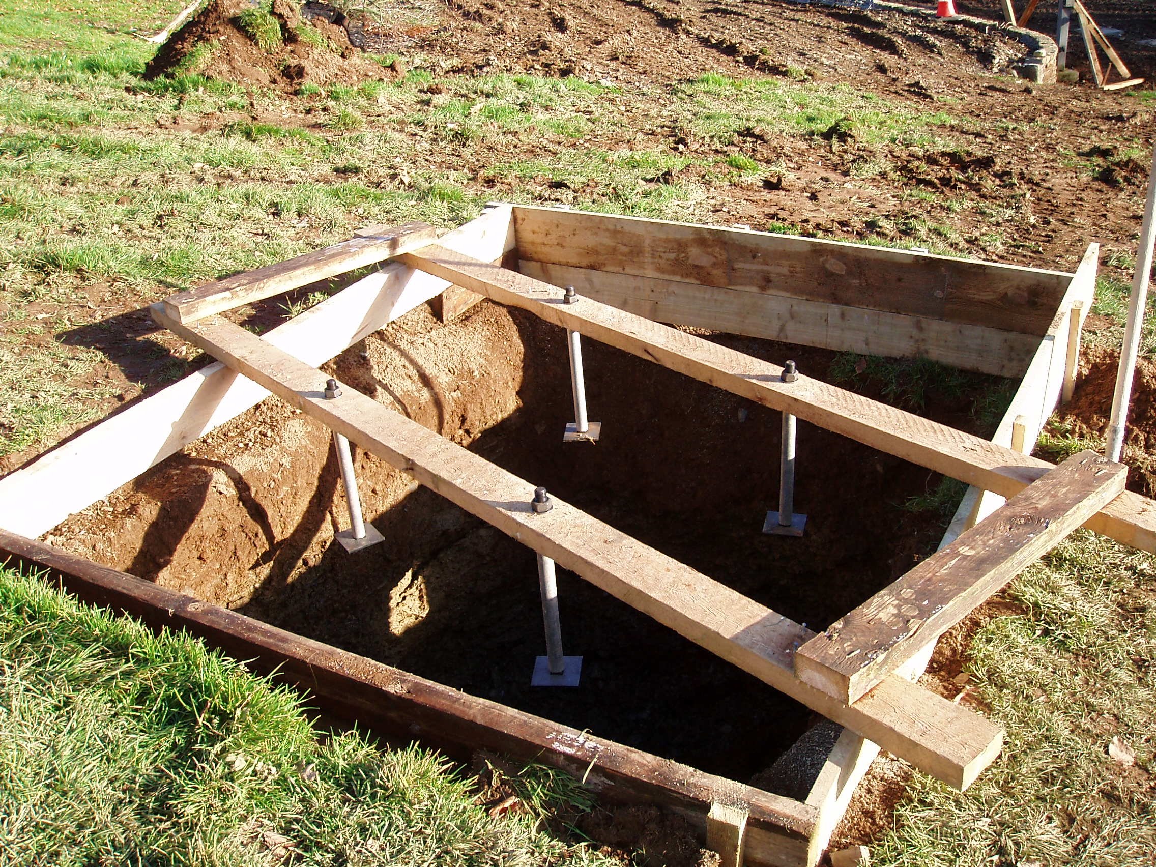 Photo from Jan G0IVZ - shuttering and bolt template prior to
fixing
Photo from Jan G0IVZ - shuttering and bolt template prior to
fixing
You can mix the concrete yourself or pay for 'Readymix' - try to estimate how much you will need in cubic metres (called 'cubes' by the suppliers) - the smaller Readymix lorries can carry 3 cubes i.e. about 7 tonnes, which should be enough for a tower base - however you have to consider this important question - can the Readymix lorry get close enough to the hole for pouring the concrete? It can be pumped over a reasonable distance but you would have to tell the suppliers this in advance. A digger with large front bucket can be used to ferry the liquid concrete to the hole if necessary.
*Make sure you are well prepared for the Readymix concrete to be poured - the lorry driver will be impatient to get onto the next job and the concrete will not wait for you if you are not properly prepared!* If you are mixing the concrete yourself, position the mixer so that the concrete can be poured straight into the hole if possible, to save time and effort. Over-estimate how much cement, sand and gravel you will need, because ideally the whole base should be poured at once - not in layers over a period of time - the layers might not bond properly to each other, resulting in a weaker base. See 'feedback' page
It will save time if you can also use the same batch of Readymix concrete to secure the three (or 4) guy stakes - see section 10 below.
I would avoid 'wall-mounted' Versatowers - in a storm the forces involved could easily damage a normal wall - if you do get hold of a wall-mounted version, consider obtaining a ground-post or base-plate for it. There may also be problems with a trying to mount a large antenna on a wall-mounted tower. Also avoid other types of lattice tower which use a single winch for tilting and raising/lowering.
4. Preparing the tower for installation
Before you install the tower on the post, it is worth examining it carefully and sorting any problems which might mean you have to dismantle it at a later date.
Firstly, it is false economy not to replace the wire ropes if they show ANY signs of rust or have any broken strands or weakened eyelets at the ends. A wire-rope breaking when tilting or raising the tower could injure you or others and could destroy an antenna or rotator worth hundreds of £, as well as seriously damaging the tower. Early galvanised wire-ropes had a string core which was designed to absorb lubricant, so it was a good idea to soak the wire ropes in engine oil for a day or two, then coat them with grease along their entire length during installation - some parts of the wire ropes are difficult to get at once the tower is assembled but aerosol spray grease is helpful. Modern wire ropes have a (usually blue) artificial fibre core which is less absorbent of oil. You can buy stainless steel wire ropes, but I have always had a worry about their use if the tower is regularly extended or luffed - see the separate webpage about Stainless Steel wire ropes. Examine the ferrules/eyelets carefully - they often have a date code stamped on them. Some tower owners replace all the wire ropes every 3 years or so - a good policy.
Secondly, remove all the pulleys, inspect and replace any pulleys or bolts that are worn, then replace them with a thick coating of graphite grease on the bolt shaft, pulley hole and pulley sides. Remember the difference between a 'bolt' and a 'set-screw' - a bolt has only part of the shaft threaded, whereas set-screws have the whole shaft threaded. Always use high-tensile steel bolts everywhere on a tower. Stainless steel hardware can be used in most locations to reduce corrosion, but is not advised for bolts that are under severe loading. Some bolts/nuts on a Versatower cannot be fully tightened e.g. pulley-mounting bolts (fully tightening them would prevent the pulley from turning) - use lock-nuts or self-locking nuts e.g. Nyloc nuts, on these bolts.
 Next, examine the lattice sections - if there are any breaks
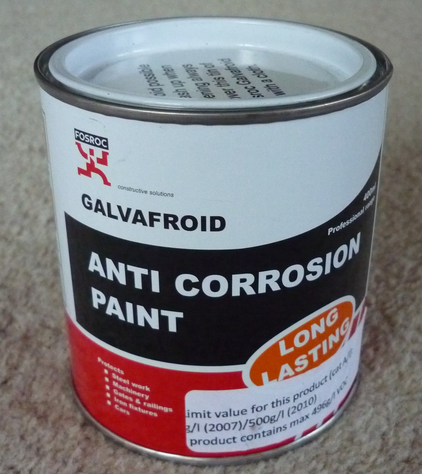
in the galvanising (which does wash off eventually) they should be painted with
Fosroc
'Galvafroid' cold-galvanising paint (fairly expensive paint - August 2018 price
= £31
for 400mL) Some owners take this a stage further and
paint the entire tower e.g. NATO matt green or forest green to reduce the visual impact slightly.
Painting does have the disadvantage that if the paint surface cracks, rust can
form underneath the paint and go untreated. Check the welds on all the
cross-bracing and the overall straightness of the sections if the tower is old
or had a hard life. A bent horizontal or diagonal bracing strut can be
straightened by using a piece of wood and a 2lb hammer, but it often difficult
to position the wood because of other bracing struts.
Next, examine the lattice sections - if there are any breaks
in the galvanising (which does wash off eventually) they should be painted with
Fosroc
'Galvafroid' cold-galvanising paint (fairly expensive paint - August 2018 price
= £31
for 400mL) Some owners take this a stage further and
paint the entire tower e.g. NATO matt green or forest green to reduce the visual impact slightly.
Painting does have the disadvantage that if the paint surface cracks, rust can
form underneath the paint and go untreated. Check the welds on all the
cross-bracing and the overall straightness of the sections if the tower is old
or had a hard life. A bent horizontal or diagonal bracing strut can be
straightened by using a piece of wood and a 2lb hammer, but it often difficult
to position the wood because of other bracing struts.
Examine the head unit and how it will mount onto the top of the top tower section - check that the 3 threaded legs fit properly into the 3 sleeves on the top section (on some towers the head-unit is mounted using 3 high-tensile bolts through sleeves welded onto the outside top of the top section, with the threaded legs of the head-unit inside the tower section tubing). Check that the sides of the head unit can be made parallel to the sides of the top tower section - usually there are 2 nuts on each leg of the head unit and you can adjust them to make the head unit parallel. It is also much easier at this stage to check how your rotator, thrust bearing (if used) and stub-mast will mount onto the head unit. It is useful to weld a 40cm piece of 10mm steel rod, with a loop at the end, onto the side of the head unit, to space the cables away from the tower sections to help prevent snagging and damage to the expensive coax and rotator cables when raising/lowering.
Check the condition of the rope which moves the catcher plate - again it is false economy to not replace this rope if it is frayed or damaged - use modern high-strength cord or 3mm stainless-steel wire rope. Grease the catcher plate hinge.
Check the condition of the large hinge pin which secures the tower base section to the tower post - grease it thoroughly with graphite or copper grease and check that you have the correct large washers (one each end) and 2 new split pins ready for fitting. Newer hinge pins have a flat disc at one end, so only 1 washer + 1 split pin are needed.
Check the condition of the pin and chain which secure the tower in the vertical position by passing through a hole in the extension piece, called the 'tilt-over rode', at the base of the post. (Note - this 2-piece tilt-over rode is welded onto standard ground-posts, but bolted onto the 6BP6 post) Earlier towers used a simple metal pin, with later towers using a spring-loaded pin, which needs to be kept well greased. Replacing this pin with a padlock might be a sensible security measure.


Tilt-rode, lower pulleys and pin Luffing flats
Check the condition of the double-plate assembly, called the 'luffing flats', which is bolted to the bottom of the lower section and has the pulley(s) for the luffing wire rope - the whole assembly should hinge freely and the metal spacer tube should allow the pulley(s) to turn easily, even when the bolts at each end of the assembly are tight.
The head-unit, rotator, stub-mast and thrust bearing can be mounted on the tower after the tower is mounted on the post.
N.B. See the first paragraph of section 9 before fully assembling and wiring-up the tower on the ground.
5. Grease
Grease is so important it merits a separate paragraph and a
picture!
Graphite grease is the best grease to use everywhere on a tower - with the
exception perhaps of on the wire ropes. Copper grease is almost as
good, but graphite grease avoids any possible, but unlikely, dis-similar metal corrosion
problems. Graphite grease seems to be quite difficult to obtain - see
the link below - don't let the supplier
try to sell you molybdenum disulphide grease (e.g. Castrol MS3) instead - insist on graphite
grease. Graphited Grease can be purchased by mail-order fr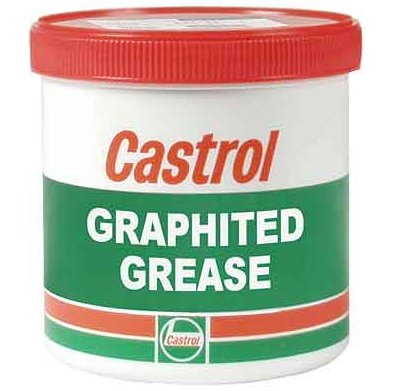 om several different suppliers
- click
here for one UK supplier - cost (Dec.2018) £9-50 for a 500g tub of Penrite graphite grease.
om several different suppliers
- click
here for one UK supplier - cost (Dec.2018) £9-50 for a 500g tub of Penrite graphite grease.
'Almagard 3202' is an excellent American-made waterproof grease used in the oil industry. Spray greases are variable in quality - some are too 'watery' and others are too 'sticky' - I found the 'Comma' brand to be quite good. Spray grease can be very useful for reaching parts of the wire ropes that are difficult to reach by hand. There are also various brands of thinner wire rope lubricants that can be applied using a paintbrush. I use up over 1kg of grease every year on the wire ropes of my towers - money well spent. A well-maintained tower will have lots of grease everywhere.
6. Winches
Try to obtain auto-brake winches (e.g. Fulton K1550 or K2550) if possible - they are expensive but *much* safer to use than standard non-braked 'boat trailer' types. Check carefully the condition of the brake pads - dismantle the winch if necessary - they have a tendency to crack, which can cause the winch to slip - this cracking might not be visible without dismantling. The brake pads can also become contaminated with grease or oil. Replacement brake pads can be difficult to source. The main winding-handle shaft of these auto-braked winches is in two parts, joined by an internal screwed thread - which unscrews to separate the brake pads from the brake discs when you turn the winch handle anti-clockwise. This internal screw thread must be well greased every few years to prevent the mechanism seizing up which would either jam the winch completely or could stop the brake pads working properly and make the winch unsafe. Study the photo of the partially-dismantled K2550 winding-handle shaft below :
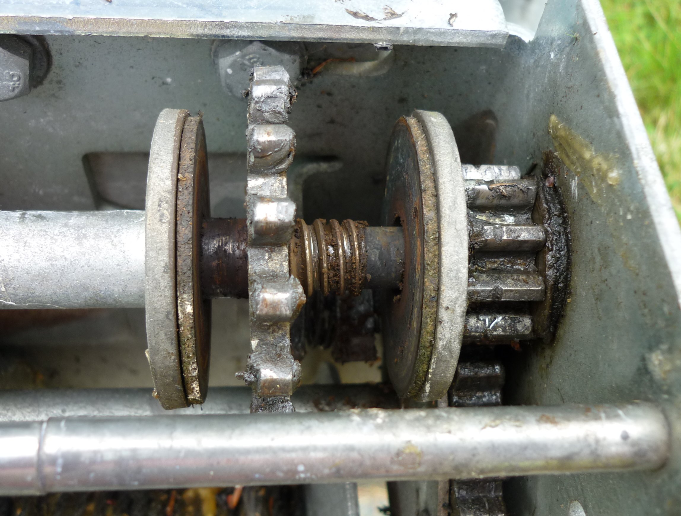 You
can see the internal screw thread (prior to lubrication), the 2 brake pads, the
gear ring, etc. To dismantle this part of the K2550, first remove the nut
holding the winding handle on (a Nyloc nut), then the nut at the other end of
the shaft, then the large circlip at the left-hand side. The gear ring cannot
clear the pawl mechanism mounting bracket without unscrewing the two halves of the shaft - as
shown in this photo - this allows you to slide each half of the shaft out
separately if necessary.
You
can see the internal screw thread (prior to lubrication), the 2 brake pads, the
gear ring, etc. To dismantle this part of the K2550, first remove the nut
holding the winding handle on (a Nyloc nut), then the nut at the other end of
the shaft, then the large circlip at the left-hand side. The gear ring cannot
clear the pawl mechanism mounting bracket without unscrewing the two halves of the shaft - as
shown in this photo - this allows you to slide each half of the shaft out
separately if necessary.
Lubricate this internal screw thread - use lots of graphite or copper grease - take care not to get grease on the brake pads or the metal faces which press against them - also lubricate the shaft to the right of the internal screw and where the gear ring turns and the brass bushes at each end of the shaft.
When re-assembling, it is necessary to hold the pawl in the upward (spring tensioned) position while sliding the gear ring into position and screwing the two halves of the shaft back together.
Question - What's the first thing you should do when you buy a brand-new K2550 or K1550 winch ?
Answer - Dismantle it ! This seems a strange thing to do - but both Fulton K2550 winches I have purchased (2012 made in Mexico, 2021 made in China), in common with previously made in the USA K2550s, the amount of grease on the shafts and the internal screw threads is not sufficient for our rainy UK climate. I suggest completely dismantling and thoroughly greasing every moving surface (except for the brake pads obviously) with a lot of graphite or copper grease.
Don't bother buying the K2550X version of these winches - the 'protective covers' are useless and make the K1550X and K2550X versions more difficult to dismantle if they eventually seize up.
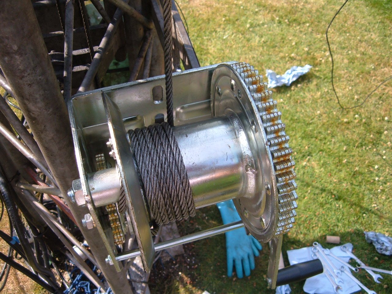
Unwind the wire ropes completely and check that the ends are correctly secured to the winch - the end should pass through the side of the winch drum and be tightly held by a clamp with 2 bolts and nuts. The latest K2550 winch owner's manual shows one turn of wire rope outside the drum i.e. clamped at the end, then one turn, then passing through the side of the drum, then a minimum of 3 turns always on the drum to prevent slippage. Take care securing the end of the wire-rope to the drum - the 2 small bolts must be the correct way round - the specially rounded heads are on the inside of the drum side, while the metal clamp and the 2 nuts/washers are on the outside of the drum side - this prevents the wire rope snagging on the threads/nuts which happens if the clamp is mounted the wrong way round. Try to wind the wire rope in even layers on the winch drum - this will prevent 'crushing' or flattening of the wire rope and helps to prevent 'jumping' when the wire rope is under tension at the ends of a layer.
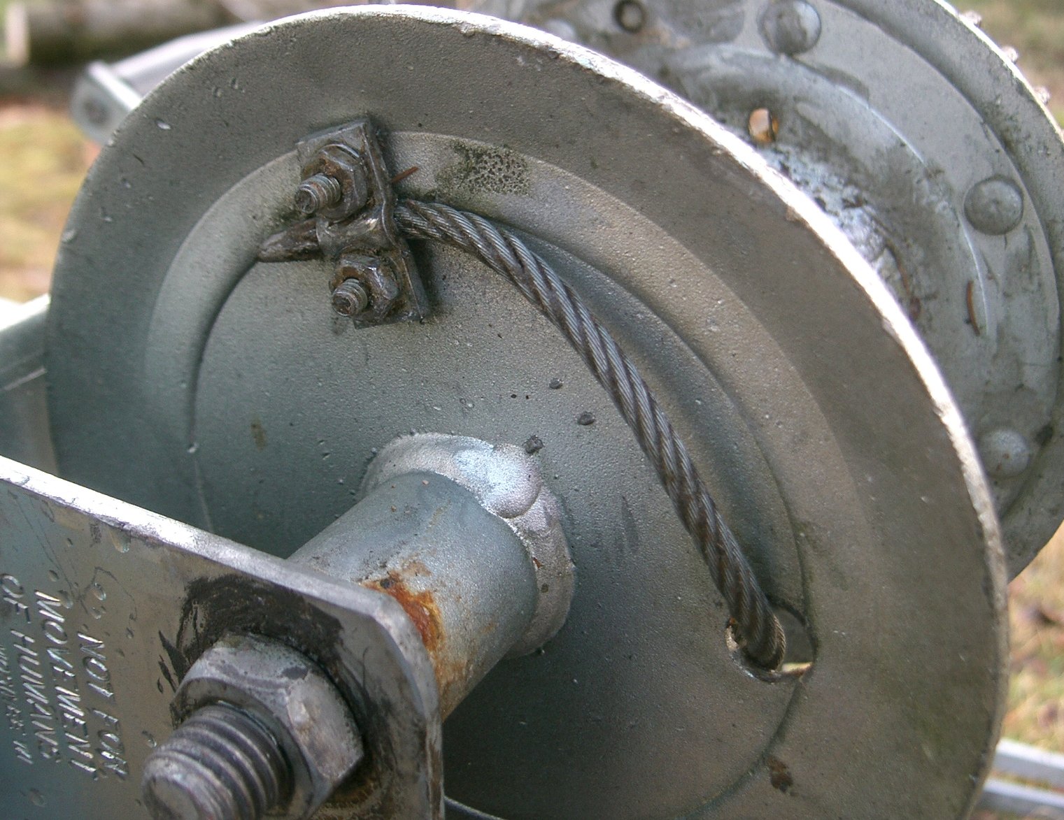
End of winch rope secured to outside of K2550 drum (without the recommended 1 turn outside the drum)
Larger auto-brake winches like the Fulton K2550 have low-gearing - for example it takes 450 turns of the handle to raise a 4 section BP80 Versatower to full height! Click here to view the K1550 and K2550 owner's manuals and parts diagrams (4MB .jpg files on external site) - thanks Martin G3ZAY.
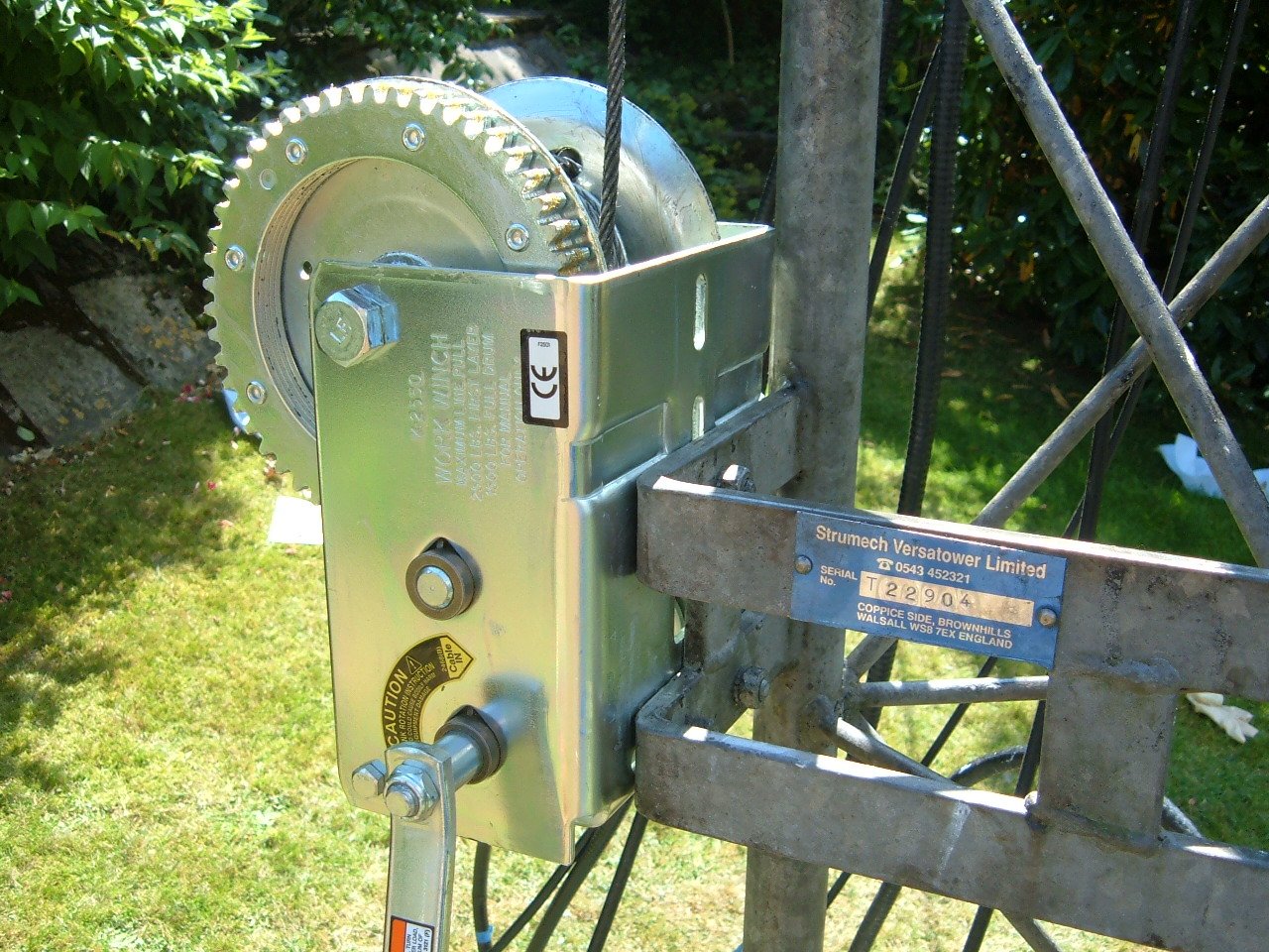
Photos from Steve GW4BLE (SK) - Fulton K2550 winch on P60HD.
Note how this raising/lowering winch is mounted with the cable drum uppermost, whereas the luffing winch is mounted with the cable drum on the lower side. See 'feedback' page
This may seem obvious, but wind the wire rope onto the winch drum in the normal direction i.e. so that the winch handle turns clockwise to raise the tower and anti-clockwise to lower it (.... at least that's what I call normal as a right-handed person!)
Check that the 'reversing' mechanism on the
winch is working properly. Some older auto-brake winches had a strange mechanism
which involved unscrewing the handle partially to reverse the action - these are
hopeless because the mechanism invariably seizes solid and is almost
impossible to un-seize, even with partial dismantling and using a gas flame to heat everything strongly.  Check and lubricate the ratchet/pawl mechanism.
Removing the handles from tower winches might be a sensible security measure, but Strumech do not recommend removing the handles from auto-brake winches if the wire ropes are under tension - with the tower resting on the catcher-plate however, this should not be a problem. I often tie the luffing winch handle to the mounting bracket with a short length of rope, just in case the something breaks in the winch when the tower is luffed over and the force on the winch brake pads is a maximum.
I like the two Pfaff 'Silver Blue' winches that I have on a M60 tower - although slightly smaller physically they *appear* more strongly constructed than equivalent Fulton winches. Click here for more info about Pfaff winches.
Electric winches (usually 12V DC powered) are becoming more popular in 2018. It's up to you of course, but I am not a great fan of these, having heard many stories of things going wrong. I think the key is never to use an electric winch remotely - always stand watching closely what is happening as the tower moves up or down. Electric winches I have seen in action raise the tower much too quickly - you would need super-fast reaction times to stop the winch if something snagged suddenly. Believe it or not, I actually like the 'keep fit' aspect of having manual winches on towers!
7. Installing the base-plate onto the concrete base
Before installing the base-plate, I recommend putting a thin (about 6mm) piece of steel bar (about 40cm long x 6cm wide) across the centre of the concrete base - this might seem strange since you have taken care to make the concrete surface smooth and horizontal, but it will allow you to adjust the 4 base-plate mounting nuts to ensure that the post is exactly vertical - some base-plate posts are not exactly at 90o to the horizontal base. You may also find that some older towers and/or combinations of tower and post mean that the post is vertical but the tower is slightly off true vertical. Apply a thick coating of graphite grease to the threads of the 4 x M24 mounting bolts.
Tower base-plates are heavy and awkward objects to move and lift - they have many sharp corners. I would recommend using a digger or loader to lift the tower base-plate about a foot above the ground, then you can lower it slowly and carefully onto the 4 bolt threads protruding from the concrete. If one bolt head is slightly out-of-position this can be moved into position by putting a nut on it and giving the nut some 'gentle persuasion' with a 2lb hammer.
Tighten down the 4 nuts (with washers underneath each), checking that the post is vertical when all 4 are finally tightened - do not overtighten these because you could distort the plate or even shear off a bolt in extreme cases. Add a lock-nut to each if possible.
Once you are sure that the post is vertical, pour watery mortar into the narrow gap between the base-plate and the top of the concrete base to grout/seal the base - you will probably have to push the wet cement into the gap - allow several days for this to dry properly. This layer of grout should not be too thick or it will bond too strongly to the underside of the base-plate and make it difficult to remove - the original Versatower manual suggests using a steel 'packer plate' about 1" thick under the centre of the baseplate, but the 6mm or so plate suggested above should be sufficient.
Drill a 0.25" hole in one of the webs, scrape away the galvanising over a small area around the hole, then bolt on the flat copper earth-strap you had previously installed. Paint this joint to reduce corrosion. This earth point is also a convenient place to connect an Andrews earthing kit for any Heliax feeders - it is a good idea to earth the outer of the Heliax at the base of the tower, because RF radiation from the antenna can be picked up directly on the outer of the cable, effectively 'bypassing' the yagi's current balun.
8. Wiring up (reeving) the tower
I have seen many wrongly-wired towers - some even dangerously wired i.e. if you kept winding the raising/lowering winch the section could actually come right out! Note - the following wire rope dimensions are for a standard BP60 Versatower - see below for uprated wire rope information and for BP80 information. ALL DIMENSIONS GIVEN ARE CENTRE-TO-CENTRE OF THE EYELETS. Click here for some info about wire ropes and a suggestion to avoid stainless steel tower wires.
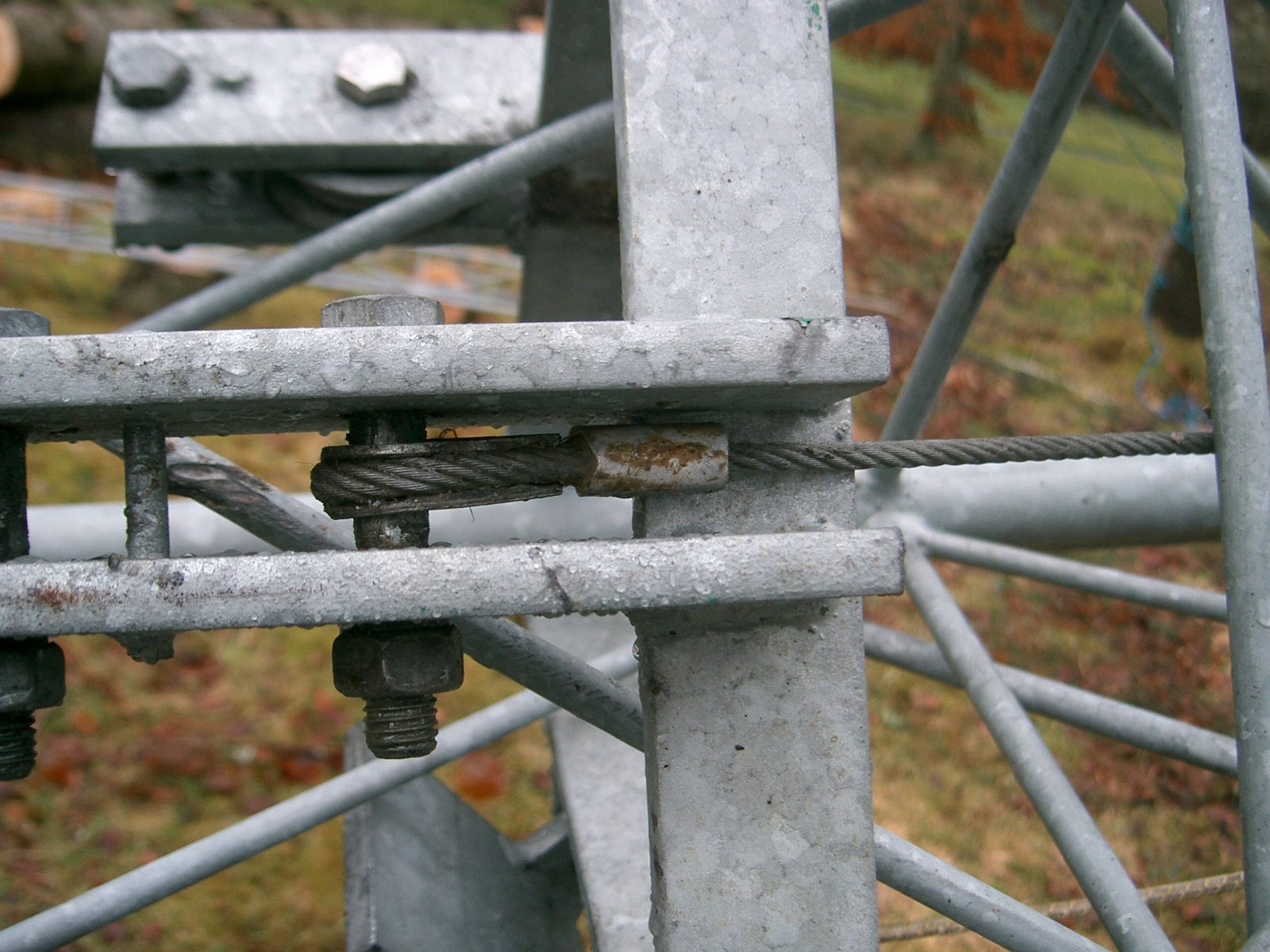
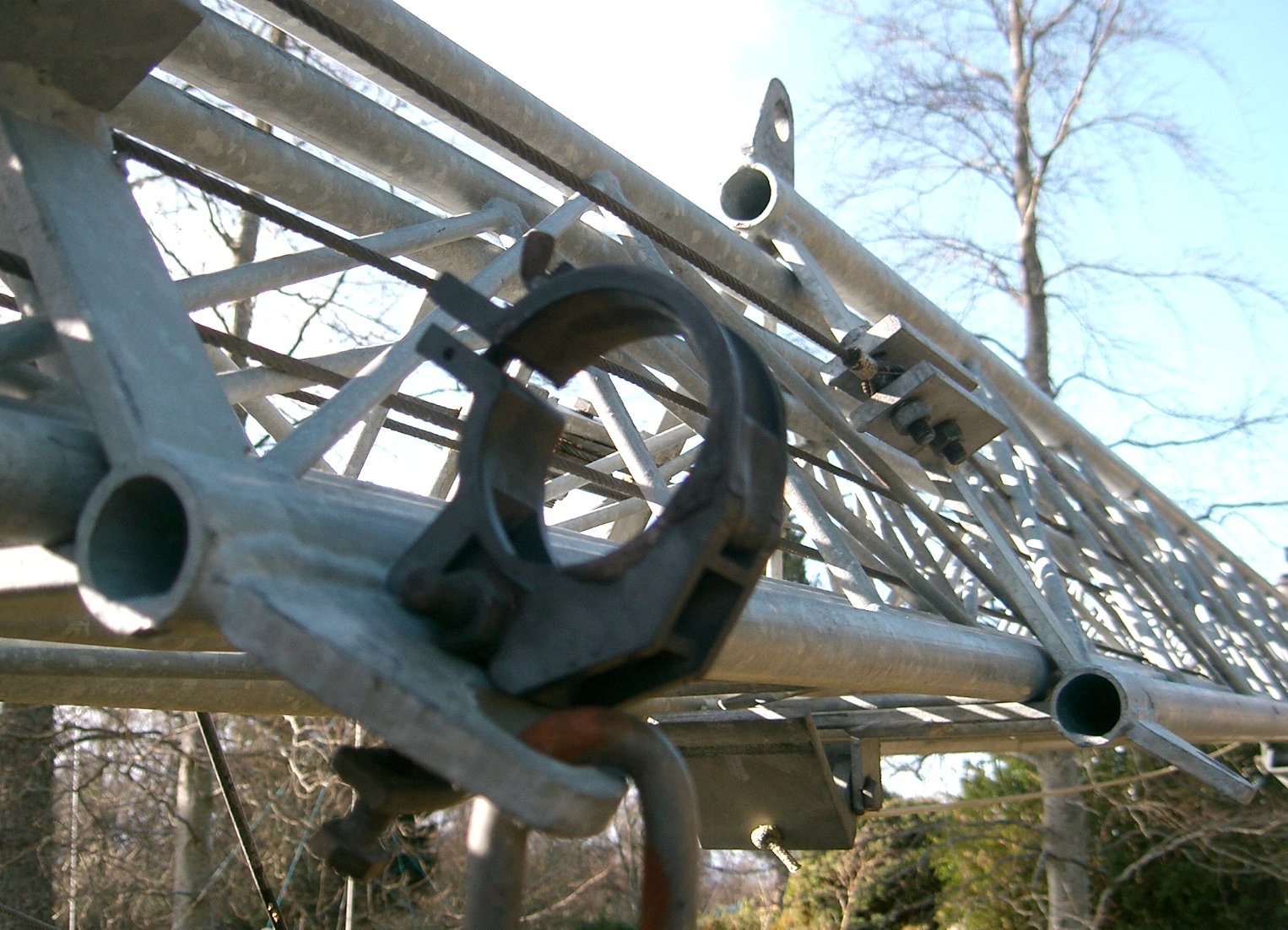
Luffing rope : 6mm x 10.4m with eyelet at one end. The luffing (tilting-over) wire rope is connected once the tower is in position on the base post. This is reasonably straightforward - it should leave the winch drum vertically - on the K2550 winch this means on the inside i.e. post side of the drum, pass under the pulley, then through the post guide tube in the vertical post, then under the first pulley on the far side of the post - then up and around the pulley on the luffing-flats assembly, then back down over the top and around the second pulley at the base of the post, then finally up to the luffing-flats again, where the eyelet on the end of the luffing rope is secured by a bolt and nut. Here is a photo of the luffing set-up :
This luffing wire rope can be uprated to 8mm without any real problems, provided you are using K1550 or K2550 winches. See the photos of the GM7R tower installation (quick link at top of page) Some winches have small diameter cable drums which would make the bending radius of the 8mm wire rope too small and would damage the rope. Having an 8mm luffing wire rope gives real 'peace of mind' when tilting over a tower with a heavy antenna and rotator on top !
Click here for a luffing (tilting over) wiring diagram for a Versatower
_______________________________________________________________________________________________
Raising/lowering wire ropes : Winch rope : 5mm x 18.9m with eyelet at one end. Upper telescopic rope(s) : 5mm x 13.1m with eyelets at each end.
* * for a BP80, the middle telescoping rope should be 13.1m, but the upper telescoping rope should be 12.6m * *
These wire ropes are outside the appropriate tower section for most of its length, but then pass inside the tower section 3 sections from the lower end - to make sure each section cannot be wound out too far. The (lower) winch rope pushes the second tower section upwards as you wind the raising/lowering winch to raise the tower - the third (upper) section(s) is therefore also pushed upwards by the upper telescopic rope(s) which are secured at both ends to the section below.
Both these ropes can be uprated to 6mm diameter if required - my personal opinion is that the original 5mm wire ropes specified are 'marginal' under most circumstances, If you think about it, when the tower is fully extended and resting on the catcher plate, the lower (winch) rope is not under tension, but the upper (telescoping) rope(s) are under continuous tension. I would recommend eventually replacing all 5mm wire ropes with 6mm ones - however there is one thing you must check before ordering uprated 6mm wire ropes - on one of the BP80 towers installed at GM7R in 2008 there was a problem with the new 6mm rope snagging, whereas the older 5mm rope just fitted the gap - this was due to poor manufacturing tolerances - several of the horizontal cross-braces were welded on just a few mm out of position, but that was sufficient to prevent 6mm rope being used on this section. Examine your tower sections carefully to make sure that a 6mm rope will not snag the way this one did.
Click here for a wiring diagram (raising/lowering) for the 13M20 60-foot (18m) Versatower
Here is an important quote from Fred G4BWP "The key thing about reeving the ropes is the fact that it passes over the 3rd horizontal bracing from the bottom. The other 'Gotcha' is that there is usually a pin in the bracket holding the top pulley and often the rope is passed over the pin (should be under) so the rope runs (badly) on the pin not the pulley. Sooner or later on the first wind up the rope breaks - been there, done that !"
The 'pin' that Fred refers to in the quote above is a 'rope guard pin' - a short metal rod above the pulley, designed to stop the wire rope from jumping off the pulley and jamming. Make sure that every rope moves in the pulley groove, not rubbing against a rope guard pin. There is a problem if you try to squeeze every last foot of height out of the tower by bringing the wire ropes through the lowest or second-lowest horizontal bracing - the wear and tear on the wire rope will be increased - even with correct reeving, you can still see where the wire rope unavoidably rubs against the 3rd horizontal bracing - any lower and the angle of the rope approaching the pulley is greater and hence rope wear is greater. See 'feedback' page
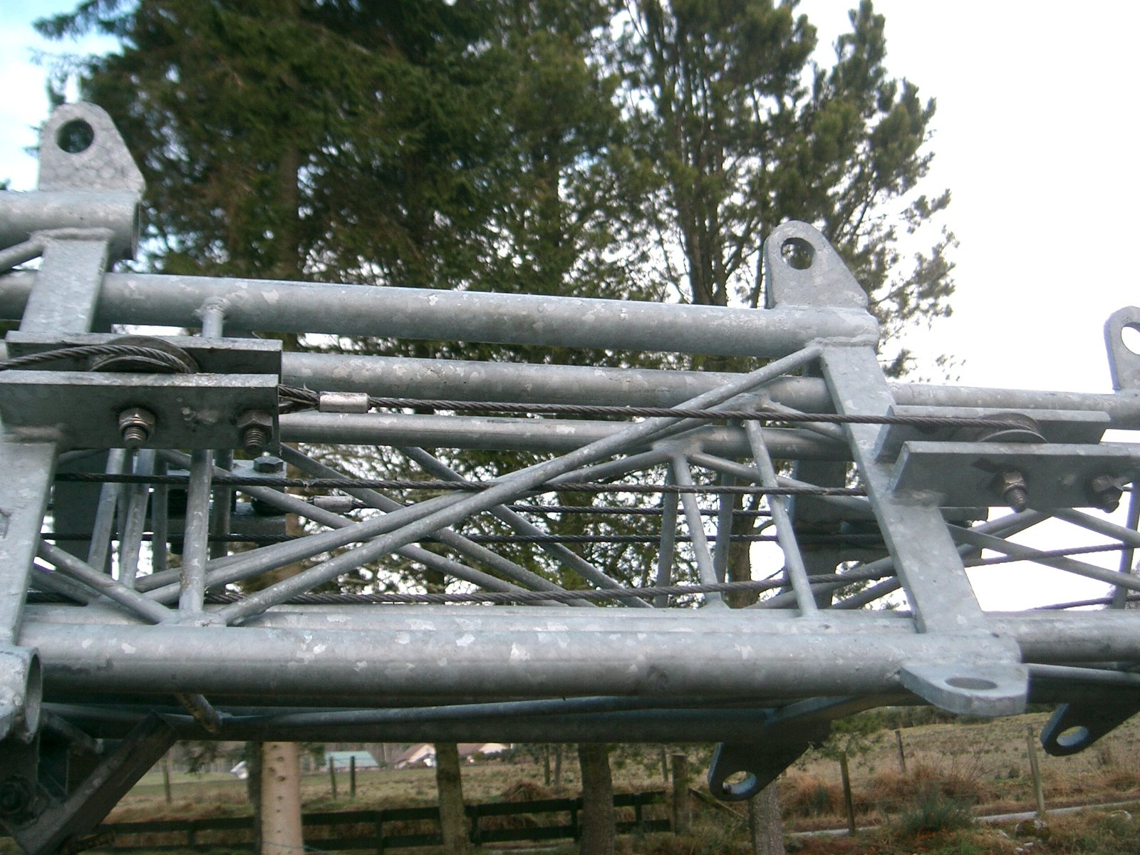
Left photo : Winch rope fixing at top of first section - note that the wire runs *outside* the rectangular section - otherwise the eyelet can catch on the second section as it moves upwards. Right photo - winch-wire pulley at top of first section, second section (with upper telescoping rope secured at both ends), third section.
9. Installing the tower on the post
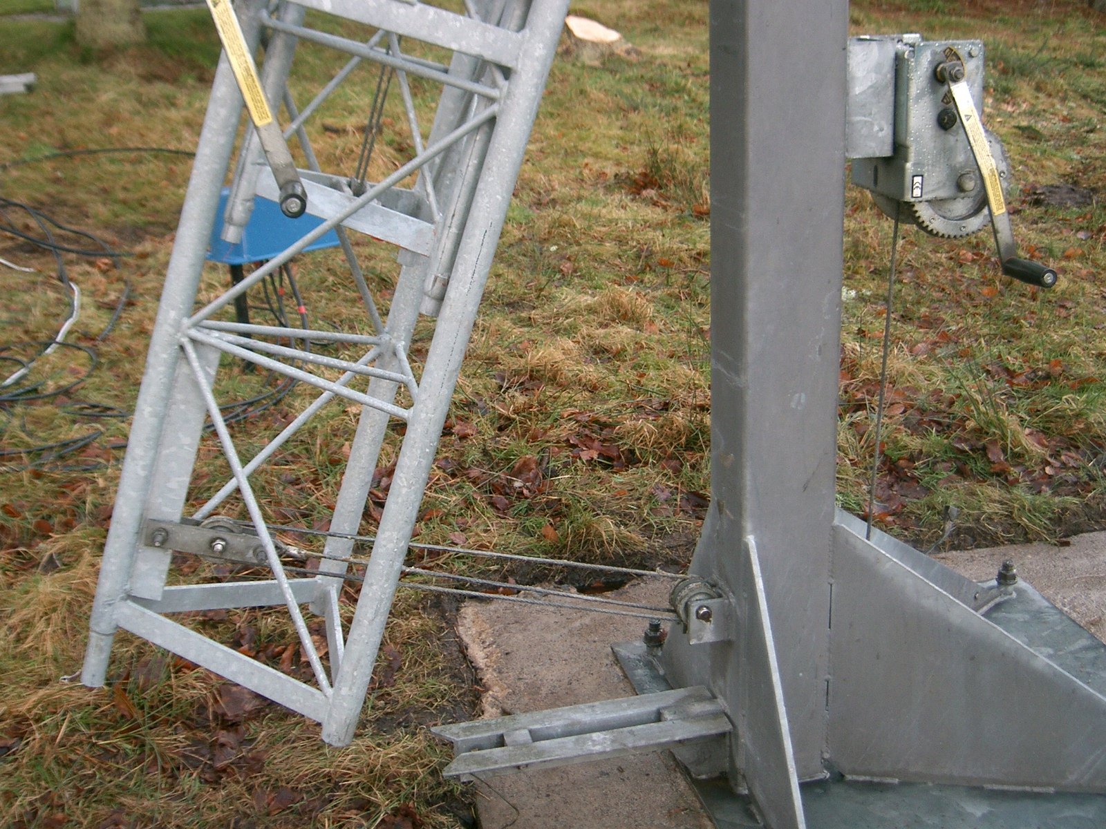
Now consider how you will lift the tower into position on the post - you can either (a) use a digger, fork-lift or loader to lift the whole tower (500kg approx for a standard P60) onto the post with the 3 sections telescoped together and pre-wired or (b) manually lift the sections, starting with the base section, then sliding each section in whilst wiring up. Both methods work well - for method (b) however, you will need at least 3 strong men to lift the base section of a heavy-duty P80 into position. In either case the tower lugs need to be fairly accurately lined up with the hole on top of the post before the large hinge pin can be inserted.
Lifting the tower sections and installing them one at a time is actually quite an easy method if you don't have machinery to lift the whole tower - the wire ropes usually do get 'snagged' in between the legs of the sections when the tower is horizontal on top of the base post, but can be un-jammed with a screwdriver. However, take care not to damage the wire ropes when doing this - one other method is to use tie-wraps to hold the wire ropes centrally until the tower reaches the vertical position, but you have to have a method of cutting/breaking the tie-wraps.
See section 12 below before allowing the end of the tower to drop below the horizontal.
10. Guying the tower
I would recommend that all lattice towers are guyed, even
those sold as 'free-standing' - the head-unit + rotator + cables + stub-mast +
thrust bearing + yagi
antenna(s) can easily reach 100kg, even before any wind loading effects are
considered - this is like a heavy man or woman standing on top of your tower
all the time! All these forces have to be transferred down the whole length of
an unguyed tower to the base. The guying kit supplied by Versatower with new
towers has impressive guy-wires (about 60 steel strands covered in black
plastic) but less impressive guy stakes - they are strong but only about 4 feet
long. The Versatower guying kit as supplied gives 3 guys at each level - to use the guy lugs
welded onto the tops of each section. 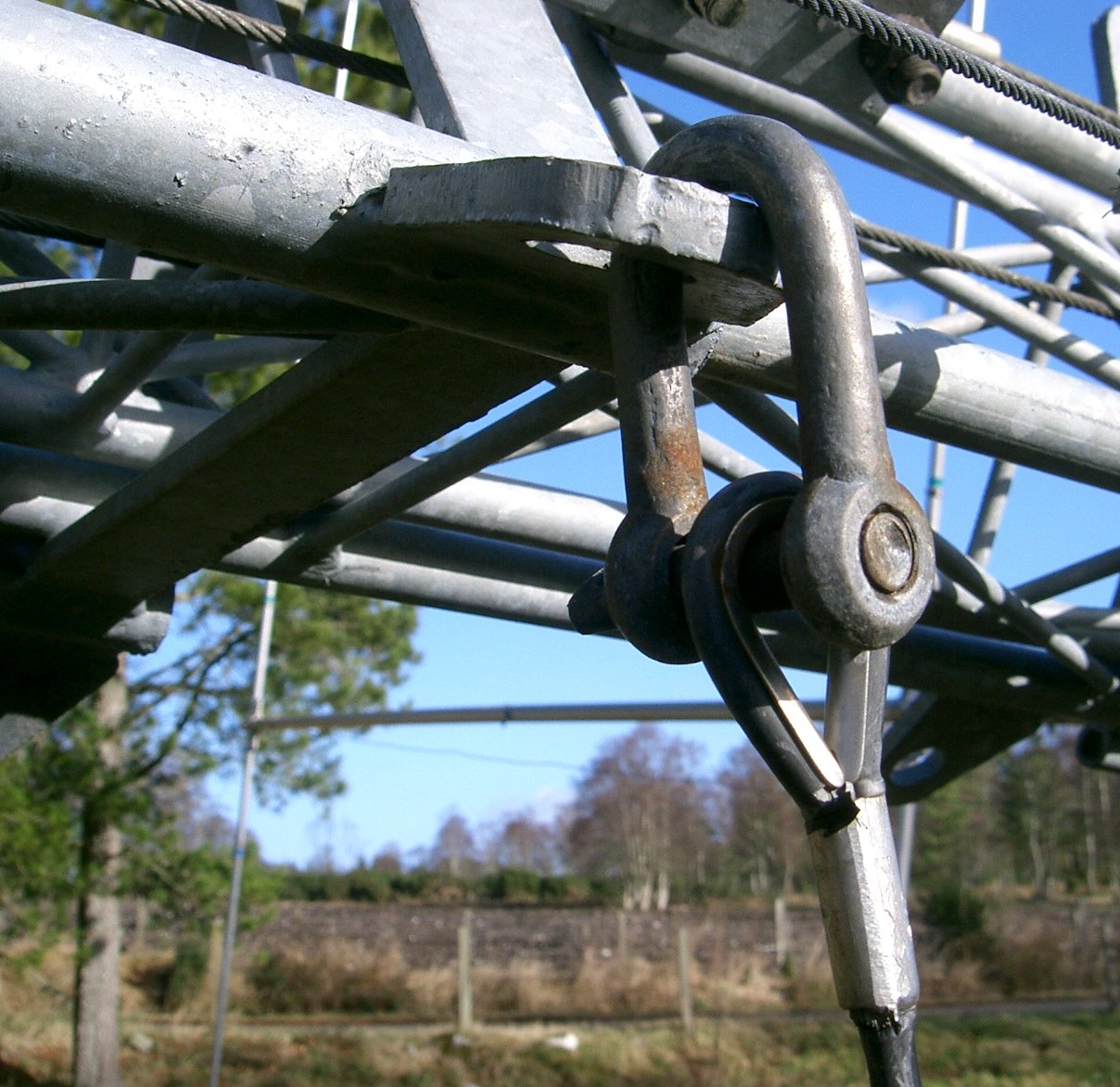 Ideally a lattice tower would have 4 guys
at 90o, but the 3 guys at 120o work well. Again, always
use concrete for the guy stakes. Some American stations with high towers have
the guy stakes vertical, but I would recommend sloping them away from the
tower.
Ideally a lattice tower would have 4 guys
at 90o, but the 3 guys at 120o work well. Again, always
use concrete for the guy stakes. Some American stations with high towers have
the guy stakes vertical, but I would recommend sloping them away from the
tower.
The photo above shows the guy fixing lug, guy shackle and the thimble at the top end of a guy wire :
It is *probably* not necessary to have a set of guys at the top of each 20' tower section - Versatower recommend only 3 sets of guy wires on a 4 section BP80 - it is guyed at the top of the first section i.e. 20', at the top of the 2nd section i.e. 40' and at the top of the 4th section i.e. 80'. Never guy a 60-foot tower only at the top - if this tower is able to lean over slightly for any reason, for example a really strong gust of wind, then the guying effect is reduced to zero and the tower can crumple in the middle. A middle set of guys prevents this from happening. The legs of a Versatower are made from 'steam pipe'-type steel, which is surprisingly soft when you try to cut it - it relies entirely on its tubular shape and the cross-bracing for overall strength. It might seem strange to guy an 80' tower at the 20' level, but this has the advantage that forces from the upper parts of the tower are transferred to the (very tight) wire guys at the 20' level, instead of all the way down to the base. (These lowest guy-wires can be made very tight because they do not pull down on any of the raising/lowering wire-ropes)
Many tower-installation articles recommend breaking up guy-wires with insulators to reduce the effect of the metal guy-wires on the performance of the antenna, but I have never found this to be necessary, provided that any yagi antenna is mounted well above the top set of guy-wires. However, the performance of a wire antenna e.g. an 80m Inverted-vee, suspended from the tower, will be badly affected by the nearby steel guy-wires.
You can buy a special device for checking the tension of the guy-wires, but generally speaking you can judge this with experience. Over-tight guy-wires will contribute considerably to the stresses on the tower and the raising/lowering wire ropes - the guys should be tight but not too tight. Even thick guys wires will stretch slightly with time and need re-tightening. Consider adding an extra guy wire from the top of the tower in the direction of the prevailing wind. Use 3 or more rope grips to secure the loop of each guy wire - this loop should be about 2 feet long or more. Use thimbles wherever guy wires rub against shackles, guy lugs, etc.
Keep all the turnbuckles ('rigging screws') on the guy-wires well greased - water has a tendency to gather in the lower half and will eventually rust/seize the turnbuckle lower thread. Thread a length of stiff wire in a spiral through each rigging screw to stop it unwinding over a period of time.
Never use Polypropylene rope for guys - it is cheap, but a disaster waiting to happen. Polyester is more expensive but safer. Kevlar is ideal but perhaps too expensive for most installations. Before buying any rope for guys, check its breaking strength and whether you can actually tie knots which don't slip - it is surprising how many strong man-made rope materials are too slippery or cannot be bent in a small enough radius to tie proper knots.
* For permanent installations, steel guy-wires are essential - you don't see any commercial towers guyed using rope! *
One disadvantage of using steel guy wires - the tower cannot be easily guyed at anything other than full height - but why have a tower unless it is at full height for most of the time ?!
11. Checking and setting the catcher-plate
Before installing the head-unit, rotator, antennas etc, I recommend that you now wind the tower to full height with the guys attached. Choose a calm day and take your time to check everything is functioning as expected. With the tower vertical but with the sections nearly fully nested, check the action and setting of the catcher-plate. When raising the tower, the catcher-plate rope should be left loose, which allows the catcher-plate to fall into position with a clunk as each horizontal or diagonal section passes it as they move upwards. This means that if the winch wire-rope breaks when raising the tower, theoretically the tower should just drop a few inches onto the catcher plate.
The catcher-plate has a bolt through it which has 2 purposes - it acts as a 'counterweight' and it also sets the clearance between the edge of the catcher-plate and the tower section which is moving up/down past it - you should adjust this bolt so that the clearance is only about 8mm. If this bolt is wrongly positioned, the catcher-plate will either not pivot into position when the rope is released, or will be too far in, preventing the tower from being lowered. When lowering the tower, I recommend holding the catcher-plate rope instead of tying it off - if a wire rope breaks you can let go of the rope (if you have good enough reaction times) - the catcher-plate *might* fall into place and *might* stop the tower sections accelerating downwards.
With the tower at full height, connect the guy-wires to the guy stakes and tension the guy wires. Crank-up lattice towers have considerable 'play' in the sections even when new, so wrongly tensioned guy wires can easily pull the tower away from true vertical. As mentioned in Section 10 above, do not over-tighten the guy wires - this creates excessive down-force on the tower wire ropes.
12. Tilting the tower over
Tilting-over (luffing) a correctly-installed tower is fairly easy - however keep a close eye on all guy ropes/wires, feeders and rotator cables - they can easily catch and be damaged. One common problem is that the wire rope can jump off one of the pulleys - usually when there is some slack in the wire rope for any reason - the wire rope then is flattened and jams at the side of the pulley and can be very difficult to un-jam using a strong screwdriver - take care not to damage the wire further. A sign of a correctly installed base/tower i.e. one which is vertical, is that the tower moves slowly and smoothly when nearly vertical and does not 'clang' into the base - however this depends on other factors as well e.g. the size/type of antenna on the tower.
Two helpful hints - before tilting the tower over, leave it extended by a few cm - this keeps the raising/lowering wire ropes tensioned which helps prevent them snagging when near horizontal. Secondly, I use a piece of wood 50mm x 50mm x 1m when tilting the tower over - this is used as a lever to start the tower tilting from the vertical position, then later as a 'brake' (wedged between the ground-post and the lower tower section) to control the last part of the tower's movement as it returns to the vertical position.
Thanks to Steve G3OAG for reminding me of a possible problem - when the tower is fully wired up and mounted on the post and tilted over - if you allow the end to drop below the horizontal the sections will try to slide out - this can be disastrous because the wire ropes become loose and can snag when the tower is tilted back up to vertical, possibly damaging the wire ropes. Guard against this by placing a crowbar or similar strong steel bar through all 3 or 4 tower sections, to prevent movement, before tilting the tower below the horizontal.
Fitting any form of massive 'counterweight' to the base of the tower to reduce the load on the luffing winch is one of the worst ideas I have heard in a long time - ridiculous (and dangerous)!
13. Raising or lowering the tower
Raising a correctly-installed tower is straightforward, but can be hard work with heavy antennas on the top. Again keep a close eye on all guy ropes/wires, feeders and rotator cables - they can easily catch and be stretched or damaged.
One problem with lowering a guyed tower is that the guys have to be loosened slightly to allow you to initially crank the tower up a few inches to clear the catcher-plate before you can lower the tower - this can place extra strain on the raising wire-ropes if you don't loosen the guys sufficiently.
Lowering a Versatower in a strong wind is not recommended, unless you really have to - often it is better to leave a correctly-guyed tower alone until the wind dies down. As soon as you lower the tower even a small amount, the effect of the upper guys is lost. The sections have sufficient 'play' for an upper section to move slightly off true vertical - the bottom of this section then rests on a cross-brace of the lower section and the whole tower jams. The raising/lowering wire rope for that section of the tower will then go slack and if you don't notice this, you are in trouble - the section could un-jam suddenly and come crashing down. If you see a slack upper wire rope, quickly wind the tower back up until the rope is tight, then ask a helper to pull gently on one of the upper guys to bring the tower back to near vertical, then you wind the lowering winch as fast as possible.
As mentioned in Section 11, don't tie the catcher-plate rope or wire to anything when lowering the tower - keep it in your hand pulled tight - if anything bad happens, make sure you let go quickly!
Another important message from Fred G4BWP "The key is to get a 'feel' for the effort required to wind up a tower, and if the resistance increases (more effort), to STOP, look, and look again, and find out why! Otherwise accidents happen. When I see people winding two-handed using a lot of effort I know there is a problem!"
14. Installing the head-unit, rotator, thrust bearing and stub-mast on the tower
You need to consider the type of head-unit which will suit whatever rotator you intend to use. Many old ex-lighting towers have a short length of 2" steel pipe welded to the centre of the lower triangular plate at the base of the head-unit, which means that you will need a lower bracket on the rotator. Most head-units allow you to mount the rotator directly onto the triangular plate with 4 or 6 bolts. Some rotators e.g. the T2X 'TailTwister' are too wide for the standard Versatower H2 head-unit, so need the wider H3R head-unit. Rotators like the Prosistel and SPID with a side-mounted motor may mean that you have to modify the head unit. Mount one or more pulleys and halyards (for wire antennas) onto the head-unit, positioning them carefully so that the ropes cannot catch on anything.
Click here for more information about some (older) common rotators e.g. T2X, Ham IV
Many rotators specify that a hole is drilled through the stub-mast and an extra bolt is added to secure the stub-mast into the top bracket of the rotator. Similarly many yagi mast-to-boom brackets have a central hole for a bolt to pass through the stub-mast - I am uncertain about these bolts - you don't want the yagi to turn independently of the stub-mast or rotator, but conversely if a hurricane strikes it might save the yagi and/or rotator from destruction if one of the clamps does turn, even if the coax is damaged in the process. Try to use the correct rotator for the size of the antenna, ideally one with a 'wedge-brake' mechanism.
There are different diameters of threaded legs on head-units -
the standard Versatower H2 head-unit has M22 (22mm) threads, but other
head-units have M20 threads and older Versatower head-units appear to have a
smaller Imperial thread. 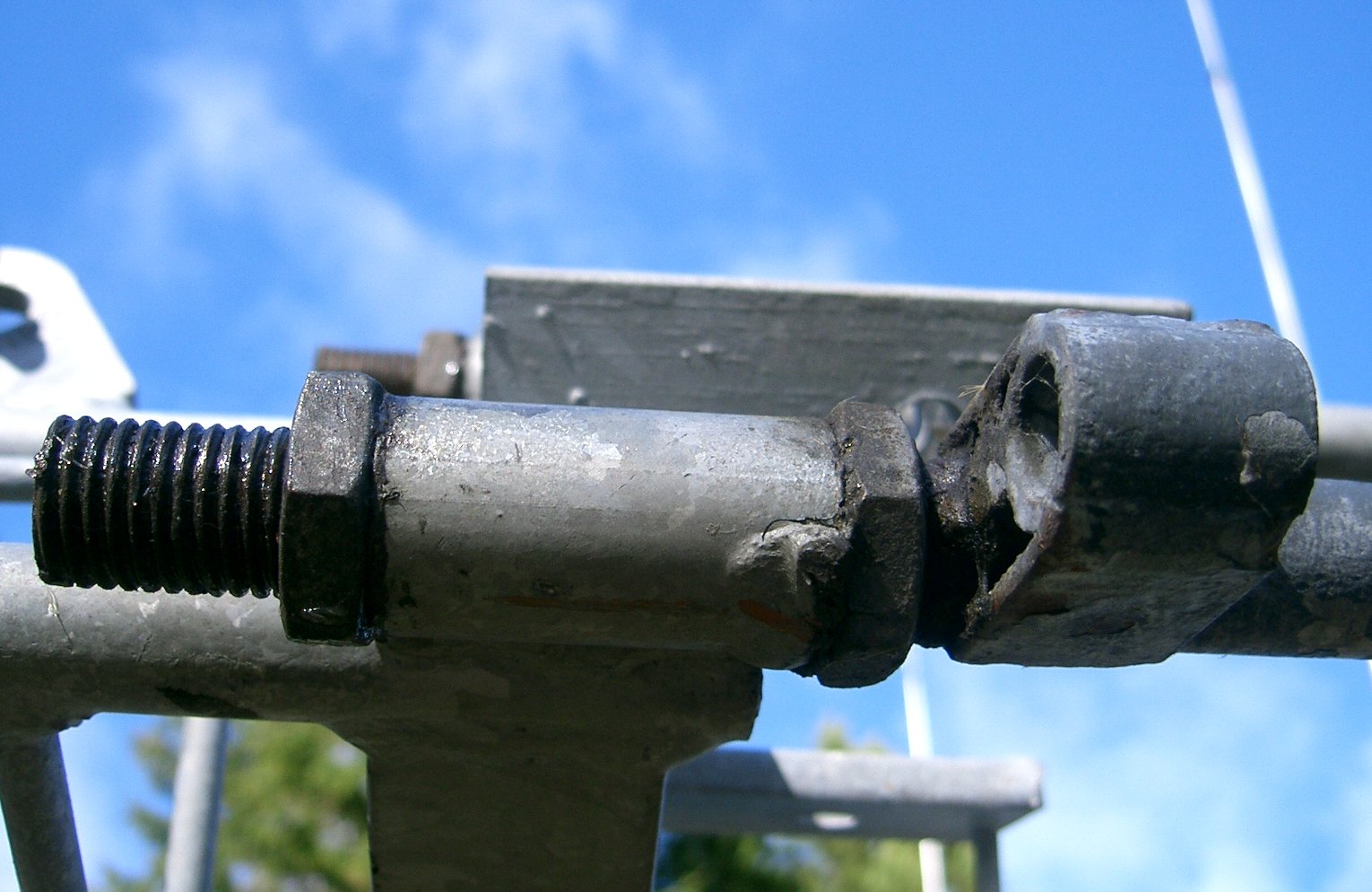 This
photo shows the threaded legs of a standard H2 head-unit - note that 2
nuts are used on each leg - this allows adjustment of the final head-unit
position to be exactly parallel with the legs of the tower. (The unused sleeve
to the right of the picture is used when the legs of the H2 head-unit fit inside
the top of the tower section and 3 high-tensile bolts are passed through this
sleeve and another sleeve on the top of the tower section to secure the
head-unit.)
This
photo shows the threaded legs of a standard H2 head-unit - note that 2
nuts are used on each leg - this allows adjustment of the final head-unit
position to be exactly parallel with the legs of the tower. (The unused sleeve
to the right of the picture is used when the legs of the H2 head-unit fit inside
the top of the tower section and 3 high-tensile bolts are passed through this
sleeve and another sleeve on the top of the tower section to secure the
head-unit.)
Make sure that these head-unit securing bolts are very tight or they can work loose in the longer term. 'Nyloc' locking nuts are a good idea here.
Before installing the rotator on the head-unit, consider dismantling the rotator and re-greasing the ring(s) of ball-bearings and the gears. This will extend the life of the rotator if done periodically, but don't overdo the amount of grease - eventually the grease will go hard and can cause the rotator to jam. Check and clean the potentiometer or other position sensor. Important - check that the rotator will rotate smoothly through 360o (or 450o for some types) *before* installing the antenna on the stub-mast. Waterproof the connector block or plugs carefully.
Thrust bearings are essential for a permanent installation - mounted at the top of the head-unit they *should* remove all side-forces from the rotator and can also take the vertical load of the stub-mast + antenna, but often most of this vertical load can be taken by the rotator itself without damaging the rotator. Thrust bearings have a finite life - water travels down inside them, into the ring of ball-bearings and rusts them eventually - periodically spray the gaps with grease to help with this problem. There are several types of thrust bearing available - choose the larger type with 2 sets of stub-mast fixing bolts and lock-nuts. Do not over-tighten the 4 thrust bearing mounting bolts - it is very easy to crack the aluminium alloy casing of the thrust bearing. For example, see https://www.wimo.com/rotor-accesories_e.html for more information about which thrust bearings and other mounting hardware are available. (The 'absorber joint' might be a useful addition mounted below the rotator)
Stub-mast - this should be a balance between weight and strength - typically an aluminium scaffold pole with 0.25" wall thickness will work well and be strong enough for most HF yagi installations. Note that 'scaffold' poles are slightly less than 2" outside diameter - normally 48.3mm - with certain rotators (e.g. hy-gain T2X) you may need to shim the scaffold pole stub-mast at the bottom to make sure it is central in the thrust bearing. Make sure the stub-mast is long enough if you have to mount a bracket for yagi boom bracing wires. If the stub-mast is more than about 12' above the top of the head-unit, it may be advisable to have another thrust bearing there, with guys at a shallow angle to clear any yagis below.
15. Installing a yagi antenna on the stub-mast
Below are 2 photos showing a 15m 5ele yagi (YO6.55 optimised on a 32' boom, using old Hy-Gain 204BA hardware) being installed on a mobile tower as a temporary set-up for CQ WW SSB 2006 - note that the head-unit has no thrust bearing and the whole tower is guyed by 15mm 3-ply ropes - both unsatisfactory for a permanent installation, but reasonable for a temporary set-up.


This method of mounting the yagi boom horizontally on the stub-mast first, then adding the upper half element and the inner part of the lower half element, works very well, especially for long-boom yagis. Don't bother with expensive hinged mast-to-boom clamps, etc - this method is the best - even for complicated trap yagis like the useless TH7DXX, beam-in-two-directions-at-once yagis like the KT34XA, or riveted antennas like the C3 etc. You have easy access to all vital bolts, can easily join the coax to the feed-point, can adjust the tension in any bracing wire or rope, etc. The other parts of the lower half elements are easily added progressively as the tower is tilted upwards in stages. Once the yagi is fully assembled, the tower is tilted towards the vertical far enough for the rotator to turn the yagi so that the reflector is parallel to the ground e.g. about 2m off the ground. This allows an initial check on the SWR and resonant frequency to be made - both should be close to the final values obtained with the antenna horizontal at the full height of the tower.
Note the coax loop - some installations use a 'spiral' of coax around the outside of the head-unit, sometimes protected inside a length of hosepipe, which 'winds' or 'unwinds' as the antenna is rotated - however I have found the simple loop as shown, provided it is not too long or too short, to be more reliable and less likely to sag and catch on any bolts, etc. This RG213U loop connects to LDF4-50A Heliax cable (not shown) just at the base of the head-unit - the weight of the Heliax is taken by a short support rope tied to the side-arm on the head-unit. Never apply tiewraps directly to coax cable - they have sharp edges which will eventually damage the cable - put a few layers of PVC tape then the tiewrap on top. Use UV-resistant tiewraps. Seal all coax connectors with self-amalgamating tape (stretched 50% and overlapped 50%) covered with PVC tape - make sure the taping extends 2" or so along the cable on each side. Never use self-amalgamating tape on top of PVC tape. Self-amalgamating tape degrades with prolonged exposure to UV - some makes are better than others for resistance to UV. In commercial installations, multiple layers of self-amalgamating tape then PVC tape are painted with 'Scotchcote' or similar varnish.
Coax and Heliax mounting clips are available, but are usually not really suitable for a tower which can crank up/down - I recommend the type which have strong plastic rings about 3" i.d. - one at the top of each telescoping tower section prevents the coax cables + rotator cables from moving about too much in a gale, but still allows these cables to move freely when you are raising or lowering the tower. The photo above shows a coax bracket clamped to a guying lug.
16. Mobile towers
Mobile towers (M60 etc. series) are often used for portable operation, or where a permanent Versatower would be impossible because of local restrictions. Second-hand mobile towers are often in poor condition, having been used in industry with minimal maintenance, untrained operators and usually stored outside. They are usually a Base-plate Versatower mounted on a trailer, with a 50mm ball or 30mm ring hitch and (hopefully) a braking system. 3 outriggers are pulled out from the trailer to stabilise the mobile tower when in use.
My first mobile P60 was in poor condition - the outriggers had been neglected and had rusted inside the trailer legs - even 2 x 200HP tractors pulling with chains could not pull one of them out, so I will have to cut the end off and slide in a smaller-size rectangular section. At the outer end of these outriggers are adjustable vertical legs - a bit like caravan jockey-wheel mechanisms - these are usually damaged on older mobile towers.
There are about 5 different styles of trailer that I have seen - some are easy to tow with a family car, whereas others have poor balance or excessive nose-weight which means you need a 4x4 to pull them safely. The type with the longest distance horizontally between the tow-hitch and the tower base are the easiest to tow. Even a mobile P60 is a heavy object to pull - a lot of the weight is quite high above ground level - the trailer braking system needs to be kept in good condition and cornering done cautiously !

Photo from Nick G4FAL (Sheffield ARC tower)

Photo from Mark G4AXX - Versatower M100, in the Plextek car park
17. Maintaining the tower
A well-installed tower and antenna system should only need maintenance every few years. However the condition of the wire ropes is crucial, so inspect them regularly for any signs that the grease on them is thinning or has washed off completely and keep them well greased. Similarly, inspect the condition of the winches carefully and re-grease them if necessary. Most of the maintenance tasks are detailed in the above sections.
18. Safety notes
NEVER climb a crank-up tower when it is extended. The extra loading from your body weight could be the final straw for stressed wire ropes. There is *always* some other way of overcoming the problem - one common problem is that the catcher-plate rope breaks and the tower is stuck on the catcher-plate and cannot be lowered - don't panic - just get a ladder and replace the rope.
Similarly, never stand under a partially tilted-over tower - the forces in the luffing wire-rope are very high in this position and it could break.
The most important safety advice is to check the wire ropes regularly - most crank-up tower accidents involve wire ropes breaking - personally I think the lower i.e. winch rope should be uprated from 5mm to 6mm - this will still fit the winch drum and pulleys etc. - this winch rope has to lift 2 or 3 tower sections (+ head unit, rotator, stub-mast, antennas, coax, rotator cables and guys) and is always under a lot of stress.
Never try to catch the handle of a non-auto-brake winch if you let it go - the tower will start accelerating downwards and the handle will spin dangerously - I have a scar on my palm from learning this lesson - this is the main danger of not using auto-brake winches - sooner or later you will let go of the handle accidentally, no matter how hard you concentrate on not letting go.
If using an electric winch, devise some procedure which ensures that you don't try to winch the tower up or down if the sections are tied together or the coax cables are tied off. Check carefully for snagging of the coax etc before pressing the switch. Ideally watch the whole procedure carefully, STOP and investigate immediately if the winch seems to be overloaded for some reason.
I use large 'Danger - electric shock risk' signs stuck onto the side of the ground-posts to discourage possible vandals!
Take care using auto-brake winches in heavy rain - the water can act as a lubricant on the brake pads and can make them slip.
19. Feedback and comments from the uk-contest reflector Click here to view this separate webpage
Comments and extra information from MW1LCR, G4ZTR, VP8NO, GM3SEK
20. Tower and antenna photos page Click here to view this separate webpage (external site)
Photos from G3BJ, G6PZ, G0IVZ, GW4BLE, GM3ZBE, G4AXX, G6CSY, M0MCX, G0WCW, G4UJS, G3TXF, MW1LCR, MW3JNV, MM0DXC, 5B4AHJ, F5APQ
21. Common tower problems and 'tower disaster' photos Click here to view this separate webpage (external site)
Photos from G6PZ, GW4BLE, GM4YXI, G0WCW (M6T), G3XSV (EJ2MT), MW1LCR, G3BJ, GM3SEK, GW0GEI
22. Peter Howson GM8GAX's story and pictures - renovating a Westower. Click here to view this separate webpage
23. Jacques Rocourt F5APQ pictures - Construction du nouveau pylône Versatower Click here to view this separate webpage (external site)


19th December 2018 - I hope you found these webpages useful.
73 Chris GM3WOJ GM2V ZL1CT This webpage/information © Chris Tran GM3WOJ 25/10/2006