Mixer Terminations
1. Introduction
All types of mixers need some form of defined termination but in passive double balanced mixers (DBM) this is particularly important. Regardless of whether the DBM is based on schottly diodes, FETs or Analog Switches the provision of the correct termination impedance over a wide frequency range has a direct bearing on the strong signal performance and intermodulation distortion. A good rule of thumb is that the mixer should be correctly terminated from the lowest possible frequency in use to at least five times the highest frequency in use.
The simplest form of DBM termination is a 50 ohm resistor but this increases the overall loss and is therefore inefficient. An alternative is to use a wide band, low noise, class A amplifier with an input impedance of 50 ohms. This is better as the amplifier gain may be used to offset the mixer insertion loss. However, it does not provide any form of frequency selectivity and significant levels of local oscillator leakage at the intermediate frequency (IF) port of the mixer can create problems in the following amplifier at high received signal levels.
2. Diplexer
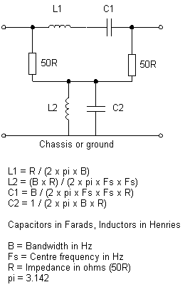
A better solution is to use a diplexer which provides the correct termination impedance over a wide frequency range and also provides a degree of frequency selectivity at the IF. The diplexer must be terminated within its passband with a 50ohm load. One example circuit is shown below right:
The 50 ohm resistors must be non-
You will need to calculate the component values for your specific frequency and bandwidth -
The signal loss in the diplexer should not exceed 0.5 dB if good quality components are used. There are alternative forms of diplexer.
3. Quadrature Hybrid Based Roofing Filter
An additional problem occurs where the receiver architecture requires a roofing filter to be placed as close to the mixer output as possible. This is usually a crystal filter with a passband chosen to allow through the widest bandwidth signal required whilst the stopband is as narrow as is economically viable. The bad news with this arrangement is that there is a very considerable change in impedance at the input and output of the crystal filter when moving from the passband to the stopband and this must not be seen by the mixer.
The filter could be isolated from the mixer with some form of amplifier but excessive gain brings its own problems in high performance receivers. A better solution is to use a pair of quadrature hybrids with two crystal filters. While this may be more expensive, the hybrids, when correctly made and adjusted, provide a precise impedance at their input and output ports over a wide frequency range. A typical circuit for 9MHz is shown below:
Values shown are for 9Mhz.
C1 = C2 = C7 = C8 = 177pF (must have 100R reactance at the operating frequency including strays so try 165pF in the form of 150 + 15pF)
C3 = C4 = C5 = C6 = 35pF
L1/L2 = L7/L8 = 0.88uH -
L3/L4 = L5/L6 = 40t of 9 strand litz wire wound on a Neosid 7100 adjustable coil assembly (5mm diameter former). Dust iron toroids may be used instead if required.
FL1 = FL2 = 9E1B 4Z, two pole monolithic crystal filter with 15KHz passband at -
L3/C3, L4/C4, L5/C5 and L6/C6 form L-
R1 = R2 = 50R
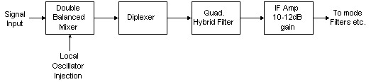
It would therefore be possible to use a low loss DBM followed by a diplexer, followed by a quadrature hybrid roofing filter, followed by a low noise, high dynamic range amplifier to provide the building blocks for a high performance HF receiver front end. If the losses are sufficiently low then an RF stage will not be required for most of the HF bands.
For high performance multimode receivers a series of these filters with different bandwidths and selected by relays may be used for roofing filters. For example, four filters with bandwidths of 15KHz, 7.5KHz, 2.4KHz and 1.2KHz (or narrower if required) would be suitable for most current modes of operation. Ladder filters would be suitable for most of the filters depending on the selected IF. At 9MHz ladder filters have a maximum bandwidth of 8 -
An example PCB layout of a four hybrid filter PC board is shown here.
4. Adjustments
In order to adjust both the diplexer and quadrature hybrid, some form of impedance measuring device is required. They cannot simply be adjusted for maximum received signal level as the signal level settings in this mode appear very broad although the impedance changes are very sharp. A low cost solution is a return loss bridge designed for the required impedance -
The following steps are required (in each step, disconnect the stage to the left during the test and then reconnect afterwards):
Connect the return loss bridge to the amplifier input and check that the input impedance is 50 ohms at the IF and across the frequency range of interest.
Move the return loss bridge to the input of the quadrature hybrid, connect the output of the quadrature hybrid to the amplifier input and adjust the filter matching components so that the pass band is flat across the desired frequency range and the input impedance if 50 ohms. It is helpfull here for the signal generator frequency to be slowly scanned across the filter passband and stopband -
Move the return loss bridge to the input of the diplexer and connect the output of the diplexer to the input of the quadrature hybrid. Check that the impedance is 50 ohms. Minor adjustments to the capacitor and/or inductor values may be necessary to obtain the best return loss.
You may now remove the return loss bridge, connect the mixer to the input of the diplexer and test / measure the mixer performance.
Information on the construction and use of a return loss bridge is shown elsewhere on this web site.
A core locking compound should be used in the variable inductors to prevent the cores moving with vibration -