This item is used to check if the impedance of an active or passive circuit is of a certain fixed value - 50ohms in the example below. It is particularly useful for checking that a particular circuit is correctly terminated, for example a diode ring mixer must be terminated with a 50ohm load over a wide frequency range. This bridge may be used to check that termination impedance.
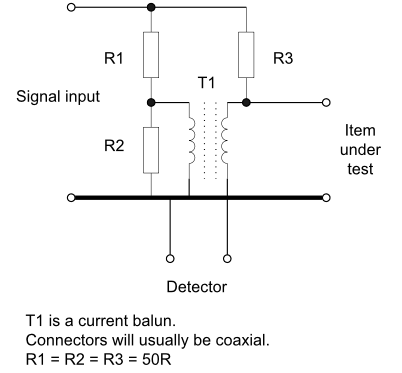
The circuit below is a simple bridge made up of three RF quality resistors R1-R3, the load to be measured and the balun connecting the bridge to the detector. RF energy is applied to the bridge and when the load is the same value as the three resistors then the RF output to the detector will be very low or zero.
1. T1 is constructed using a hi-permeability ferrite binocular core or rod or two ferrite beads side by side, or even a length of ferrite rod, with typically 5 - 10 bifilar turns of 26-30swg enamelled copper wire. The inductive reactance must be at least 250 ohms at the lowest frequency of operation and there will be a trade off between the number of turns (low frequency response) and the self capacitance (high frequency response).
The RF source is some form of signal generator and the RF detector can be a Spectrum Analyser, sensitive scope, RF millivoltmeter or RF Log Detector followed by a scope.
Good RF quality construction and components are required and the bridge is capable of operation from 1 - 50 MHz with a single balun. The balun may require changes to operate up in the VHF/UHF bands and this is left to the individual constructor. All of the resistors are 50 ohm and can be made of two 100 ohm resistors in parallel and they must be non-inductive - 0805 or larger size surface mounting chip resistors are fine.
Check the completed bridge with a known good quality 50 ohm load resistor. The output level at the detector port with the load in place should be at least 30dB below the level with the load removed.
2. The Return Loss Bridge may also be used as a Hybrid Combiner. This is a useful mechanism to combine two signals when carrying out intermodulation tests on components or receivers. Connect Signal Generator A to the ‘Signal Input’ port, Signal Generator B to the ‘Detector’ port and take the combined output from the ‘Item Under Test’ port. Both signal generators should have 50 ohms output impedances.