Return to Index
Return to Projects
This project was designed to monitor the power supply to a STSP (Short Term Special Purpose) repeater that is used for AREC purposes.
Features:
Siren alarm sound on repeater tail when supply voltage is below setpoint
Optional "roger beep" on repeater tail or beep on repeater tail to indicate failure of AC mains supply
Minimal power consumption
Compact size
Low cost
Circuit description:
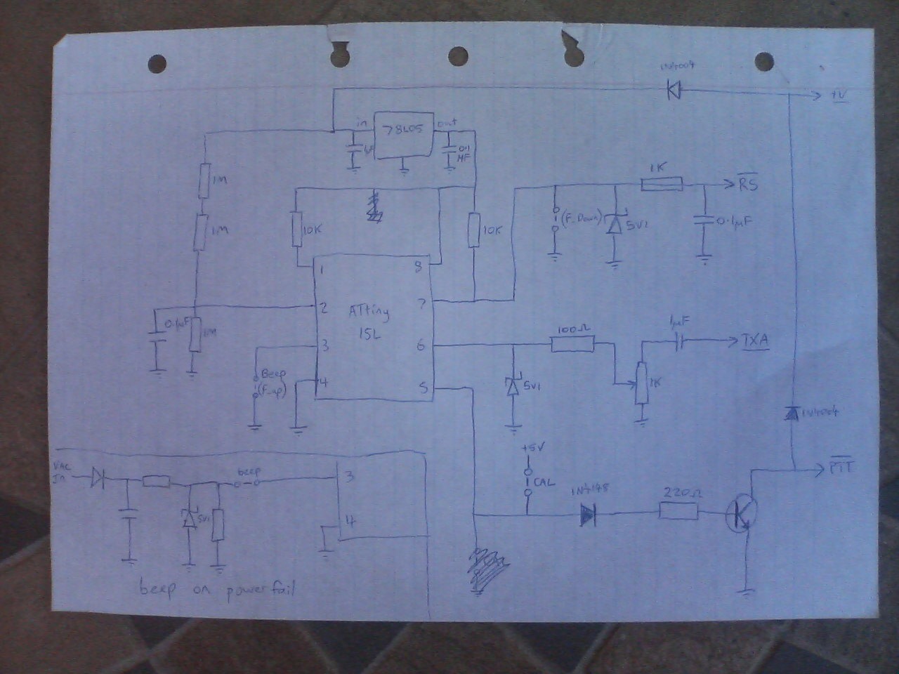
This circuit runs from a DC power supply from about 8 to 15.6 volts DC. A 78L05 regulator is used to supply a regulated 5VDC to the Atmel ATtiny15L microcontroller, this 5V supply is also used as a reference for the microcontroller's ADC when measuring the battery voltage.
The battery voltage is fed to pin 2 of the mcu, the ADC input pin, via a simple resistive voltage divider. The voltage on pin 2 = ((Vbattery - 0.6) / 3) and the ADC has an input range of 0 to 5 volts. When the voltage on pin 2 falls below the preset level (configurable from about 0.6 to 15.6 Vbattery with my circuit), a high-low-high-low siren will sound on the repeater tail to alert repeater users to the poor state of the repeater's batteries.
If pin 3 of the microcontroller is pulled low, a "roger beep" will sound on every repeater tail - this function can be used to monitor a mains power supply to a repeater with a battery backup by arranging a circuit so that pin3 will be high when mains power is available but will be pulled low in the event of a mains failure (see the example in the bottom left corner of the schematic - if you use this circuit, for safety reasons, the AC input MUST be extra low voltage eg 17V AC)
Circuit input RS (connected to pin 7) should be connected to the RX (or existing repeater controller) so that input RS is pulled low when the RX squelch opens
Circuit output TXA (transmit audio) should be connected to the TX audio input (or RX audio output) and the variable resistor adjusted for correct modulation when sending a roger beep or an alarm signal.
Circuit output PTT (pulled low to TX) should be wired to the TX (or existing repeater controller) so that it transmits when this line is pulled low.
Calibration:
Disconnect the PTT line from the TX and the RS line from the RX.
Disconnect the power supply to the repeater battery monitor board.
Connect an LED and resistor either between Vbattery and PTT or between mcu pin 5 and GND.
Remove the roger beep jumper or AC mains fail circuit, if connected to mcu pin 3.
Connect a jumper between mcu pin 5 and the +5V regulated supply rail
Connect a frequency counter to mcu pin 6.
Connect an adjustable, regulated power supply to the repeater battery monitor board's power supply input and supply it with power (12 volts nominal).
The frequency counter should read 100kHz, if it does not, you need to calibrate the mcu's internal RC clock oscillator. Increase the clock frequency by shorting mcu pin 3 to GND and decrease it by shorting mcu pin 7 to GND.
Once you are happy that the clock is calibrated, adjust the voltage on the variable power supply to the voltage setpoint that you want the low battery alarm to be triggered at (eg 12.2 volts).
Remove the jumper between mcu pin 5 and the +5V regulated supply rail. The mcu will store the new clock calibration and low voltage alarm set point in non-volatile memory and will then flash the LED connected to PTT/pin 5 at about 2.5Hz.
Once you see the LED flashing, you can safely turn off the power to the repeater battery monitor board, remove the LED and test equipment and then reconnect it to the repeater.
Assembled firmware
Assembler source code
Assembler include file
Circuit schematic
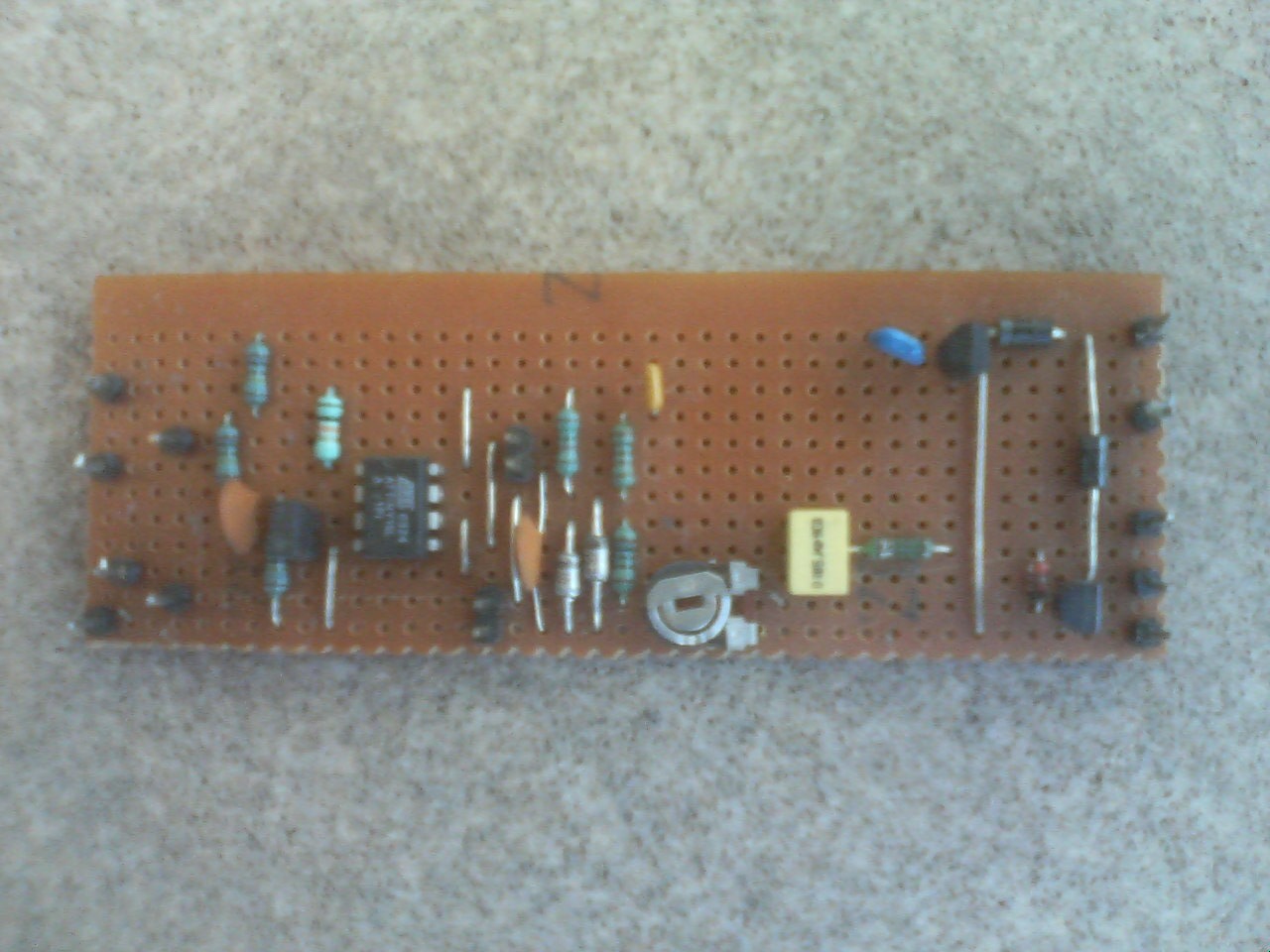
Photo of prototype
Sorry, but no PCB is available for this project.
This page last updated 3rd October 2009