TinyTrak

Links
APRS in NZ
APRS Wiki A growing resource of APRS Information
Byonics Website Home of the TinyTrak and other useful things
First APRS NZ Server (first.aprs.net.nz)
Second APRS NZ Server (second.aprs.net.nz)
ZL1AMW's webpage showing Auckland traffic at the present
ZL1AMW's webpage showing New Zealand's North Island traffic at the present
Converting a USB GPS to RS232 by ZL1VFO As used with my Tracker - A How-to with loads of pictures
Rev H UI-View Symbols Includes new Tractor Symbol
PCBs
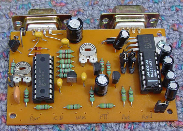
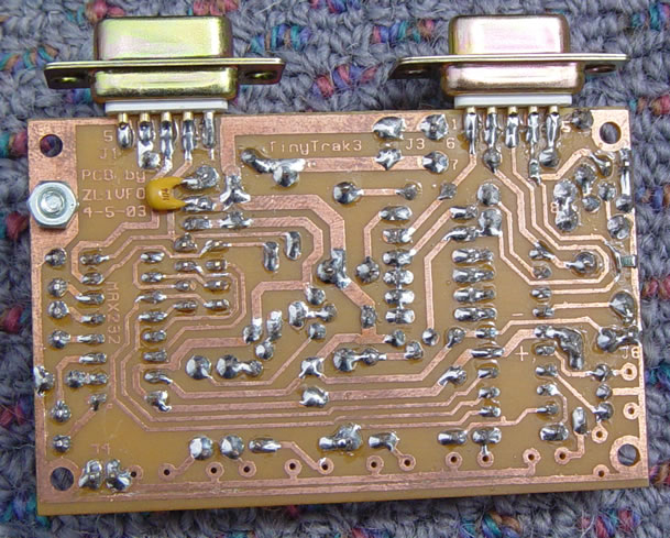
First off, here are some images of PCB artwork. The PCBs are 50mm by 80mm in size, excluding the male and female DB-9 connectors.
Click on the image to load a more detailed view.
 |
 |
 |
| Component Side |
Both sides |
Copper Side |
The trimpot in the centre of the photos is for transmitter deviation adjust. If you are able, adjust the trimpot to get about 3.1kHz deviation. Too much deviation is worse that too little. If however your radio expect something closer to line level in, instead of the mic-level this is giving it, there is a 220k resistor to the left of the trimpot and below a yellow capacitor, that can be changed to about 22k. This should give about 10 times more audio signal.
The trimpot to the far left side is the carrier detect or channel 'busy' adjust. Adjust so the Yellow channel busy light just comes on, then back it off a bit so that it stays off. When the radio is unsquelched and apeaker audio reaches Pin5 of the DB9 Female, this yellow light should come on, and go off when the squelch closes.
Jumper Notes:
(These jumpers perform the same function as in the original kit supplied by Byonics.Com
J1: The DB9 FEMALE mounted on the PCB to connect to the Radio.
Pin 1 - TinyTrak Audio Out to the Radio's Mic Audio input.
Pin 2 - An Input connected to the Radio's Carrier Detect / Busy Output, if present. 0V when Channel is Busy, >4V when not.
Pin 3 - TinyTrak PTT open collector output to the Radio's PTT input. 0V when Transmitting, >4V when in Receive/Standby.
Pin 4 - Primary / Secondary Config Switching Input, see below to connect to Ignition. +5V or unconnected selects Primary, Grounded selects Secondary.
Pin 5 - TinyTrak Audio In from Radio's Speaker Output. Use if there is no Carrier Detect Output from Radio.
Pin 6 - Ground. Connect to Radio Ground / Supply Ground.
Pin 7 - B+. Connect to Radio's +12V power supply.
Pin 8 - PTT in. When using the radio and TinyTrak with a mic, connect the Mic's PTT line to this.
Can be used to trigger a short Mic-E compressed data burst after releasing the PTT button.
Pin 9 - Presently Unused. Could be connected to JP6 for use with a Power-Control relay to switch the main Radio On & Off. Would need a TT3 chip.
J2: The DB9 MALE mounted on the PCB to connect to the GPS or WX Station. (Note a WXTrak PIC is required for WX Station operation.)
Pin 1 - Unused
Pin 2 - Serial Data In. Connect to DB9 Pin 3 at far end for computer configuration.
Pin 3 - Serial Data Out. Connect to DB9 Pin 2 at far end for computer configuration.
Pin 4 - B+. Connect to GPS +12V power wire if J7 is linked.
Pin 5 - Ground. Connect to DB9 Pin 5 at far end for computer configuration.
Pin 6 - Unused
Pin 7 - Unused
Pin 8 - Unused
Pin 9 - Unused
J3: A connection for applying +8-15 Volts supply and ground.
J4: Placing a Jumper cap on these two pins allows the LEDs to light. Removing the jumper cap disables the LEDs and saves a few mA of power.
J5: Jumper 5 allows the selection between Primary and Secondary Configurations. Pin 4 of J1 Female DB-9 connector is also connected to this. If the pin is at 5 volts, the Primary configuration is used. If at 0 volts, the Secondary Configuration is instead selected.
Suggested use - hook Pin 4 of J1 Female DB-9 connector to the ignition line _via_ a voltage divider. A 4k7 ohm resistor between Pins 4 & 6 of J1, and a 6k8 or 8k2 ohm resistor between Pin 4 of J1 and ignition +12 volts.
Alternatively, if you have some surface mount resistors available, you can cut a small break in the PCB track between Pin 4 of J1 Female DB-9 connector, and the circuit trace leading to Jumper J5. Add a 6k8 or 8.2kohm surface mount resistor across this break, and also add a 4.7kohm surface mount resistor between the same track on the micro side, and the outer ground track. The track loops around close to the ground track, so it's easy to add a resistor at this point.
J6: Jumper 6 is a 5 volt output suitable for a transistor driven relay, used to control the power to other devices (e.g. a radio) when a TinyTrak 3 PIC is used. Allows a 'power-save' mode which keeps the radio powered off while the vehicle is parked, powers up the radio a couple of seconds before posit transmission, transmits, and powers it back down again for 30 min or so. Useful when used in conjunction with J5 wired to the ignition line to select between Configurations, as above.
That output also drives a BC639 transistor capable of switching 1 amp to ground. A 15V Zener diode is connected across Collector and ground intended to clip any Back-EMF from an attached relay. The other end of the relay coil is fed from the 12V supply.
It would be a simple matter to wire this point to the unused pin 9 on the DB9 FEMALE Radio connector to allow an external (to the TinyTrak) Relay to be used, to switch the Radio's main power feed.
J7: A wire jumper which supplies +12V power to the GPS/Wx Station DB9 plug.
If required, a small hookup wire could link from Pin4 of the DB9 MALE to the output of the 7805 regulator instead, for GPSs that require only +5V to run.
Note that the PIC can be either a PIC16F84 or a PIC16F628; both are pin-equivalent, the later just has more code space inside of it.
Files
Here are some useful files
TinyTrak v1.02 Config program and Owner's Manual (TinyTrak1.02.zip - 225,498 bytes.)
TinyTrak v1.4 Config program, Hex Source code and Owner's Manual (TinyTrak1.4.zip - 229,767 bytes.)
TinyTrak v1.4 hex code (TinyTrak1.4.hex - 5653 bytes.)
TinyTrak v1.6 Config program, Hex Source code and Owner's Manual (TinyTrak1.6.zip - 228,253 bytes.)
TinyTrak v1.6 hex code (TinyTrak1.6.hex - 5939 bytes.)
TinyTrak v2 Config program and Owner's Manual (TinyTrakii.zip - 242,822 bytes.)
TinyTrak v3 Config program - No 300 baud option, PNG circuits and PCB layout, Owner's Manual, and Palm Config program(TinyTrak3.zip - 1,052,348 bytes.)
TinyTrak v3a Config program (ver1.1D) with 300 baud option, PNG circuits and PCB layout, and Owner's Manual (TinyTrak3a.zip - 928,394 bytes.)
(TinyTrak, WXTrak code and names are copywrited / trademarked of Byonics.Com)
Current U.S.A Server Time and Date
Current New Zealand Time and Date
You are visitor number  since 18/09/1999