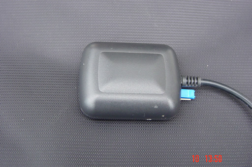
Having built a TinyTrak from scratch, I was in need of a GPS to supply the NMEA0183 data.
Luckily, I happened across some broken USB GPSs. The units still powered up, but their presence wasn't detected by the PC whose USB port it was plugged in to.
With these faulty units in hand, I bowled round to a fellow ham Harry ZL1BK, where we set upon seeing if we could modify the GPS for serial RS232 data output, and took a few photos to help document the conversion.
Harry ZL1BK had modified one earlier, and made his a little more versatile. A three pin jumper header allows him to select either standard USB data for use with his laptop, or with the blue jumper cap in the other position, he can get standard RS232 serial data for use with his TinyTrak. Consequently his GPS doesn't have the 7805 voltage regulator that I added to mine, it resides in the TinyTrak. His TinyTrak also has a USB style socket rescued from a defunct computer card to suit the plug on the end of the GPS cable.
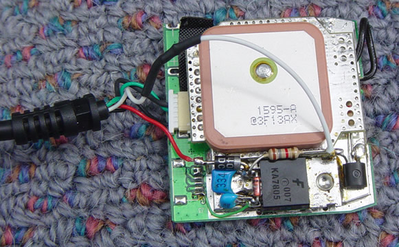
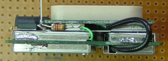
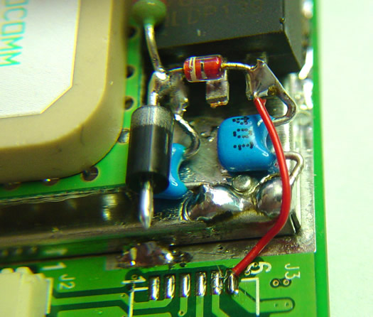
The first unit I modified showing the 5 volt regulator, it's decoupling capacitors & protection diodes, and RS232 inverting transistor (far right). The other end of the cable connects to a standard DB9 Female which plugs straight into a TinyTrak (ver 1-4) or an Opentracker 1 or 2.
Wiring is as follows...
DB9 pin
Wire Colour
Original Use
Connected via
Usage
1
Green
D+
L4 Choke
Additional LED from an Opentracker
2
White
D-
L2 Choke
Data Out, 0-12V, RS232 polarity (not TTL polarity)
3
Unused
4
Red
+5V
L1 Choke
+12V in if using regulator, or +5V in if not
5
Black
0V
L5 Choke
Ground return
6 - 9
Unused
The white wire gets moved to the side of the patch antenna when the unit is reassembled.
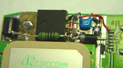
Another view showing the added green kynar wire from the inverted RS232 data point on the main PCB via a 27k resistor to the base lead of a BC547 transistor. The near transistor lead is emiter which is soldered to ground, and the far transistor lead is the collector, with a 1.8k pullup to 12V source. The RS232 data out to the TinyTrak is tapped off this collector point. The black lead to the right is the coax from the patch antenna leading to the RF board.
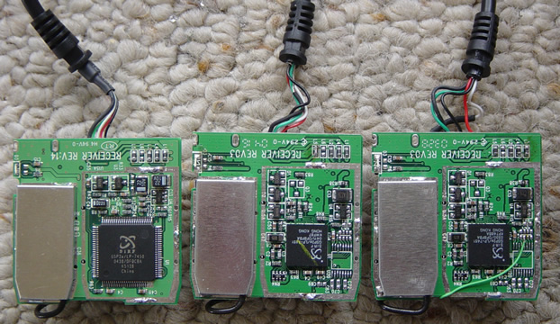
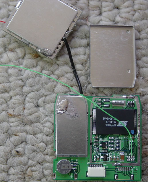
This view is of the underside of the GPS. There are apparently several versions of these, with different PCBs. The first is the type which we will be modifying, and I found out, the data pick off point is not under the bottom metal shield on this version like it is on another version. The middle unit is an unmodified unit of the type I had done before (& above), and the far right unit shows the data pick off point for the first unit I modified (same version as the middle one).
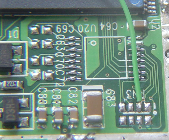
A close up view showing the pick off point for the first unit I modified. These pads are very small. You need either really good eyesight or a strong magnifier to see it, and it pays to steady your hand against something while soldering the wire to the pad, otherwise you could end up with the wire soldered to several of the pads.
OK, Firstly figure out which version you have. If you have this version, start by removing the patch antenna assembly, and the larger metal shield under it as shown. Either gently prise the metal shield up a small amount while melting the solder, doing each securing point a bit at a time, or remove the solder holding the metal can with some solder wick. Once the metal shield has been removed, a short kynar wire is soldered to the 2nd pad in from the right of the top row.
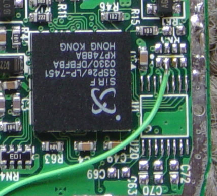
A close up showing where to solder. Notice the unused pads which appear to be for a MAXIM RS-232 level converter chip above. There has to be some serial versions of these GPSs around somewhere...
The Kynar wire has to get out from under the metal shield somehow, so we nip a small bit of the corner to allow the wire to pass through. It emerges near the top middle of the board, near the black coax cable.
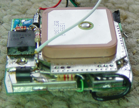
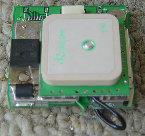
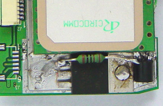
In this photo, the metal shield has been reattached, and a 7805 voltage voltage regulator has been soldered to the top of the metal shield. There is a small 'bump' in the metal shield, and the 7805 mounting hole is placed over that. Arrange the Patch antenna side by side to the 7805, and try to get the pair of them centred over the two metal shields that they will end up being soldered to. If the patch antenna is too far off centre (right in this picture), the right side of the patch will collide with the plastic GPS case when it is reassembled. Check it for fit before soldering the patch and 7805 solidly in place. The 7805 needs a bit of heat to get it's tag hot enough to take solder. The transistor can be almost any small signal transistor, in this case I used a BC547 as it was handy. The near transistor lead is emitter which is soldered to ground, the middle is the base, and far one sticking up is the collector.
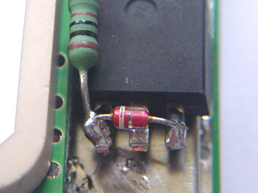
This photo shows a 22k-ohm 1/8th watt resistor soldered between the green Kynar wire, and the base of the BC547 transistor. It's wedged in between the metal shield below, and the patch antenna PCB above, and isn't going to come loose anytime soon!
A 1k pull up resistor is soldered between the 7805 12V input pin and the collector of the BC547.
Next, a 1N914 or similar diode is soldered across the output to the input. This provides a discharge path for the 5 volt rail when the 12V supply is removed. Most application notes for the 7805 seem to show this diode from output to input, so it is added here. Make doubly sure you have it in the correct way (measure the diode with a multimeter before installation to be sure) as soldering it in the wrong way will allow the 12V supply voltage to end up on the 5 volt rail. I don't think the GPS would survive that...
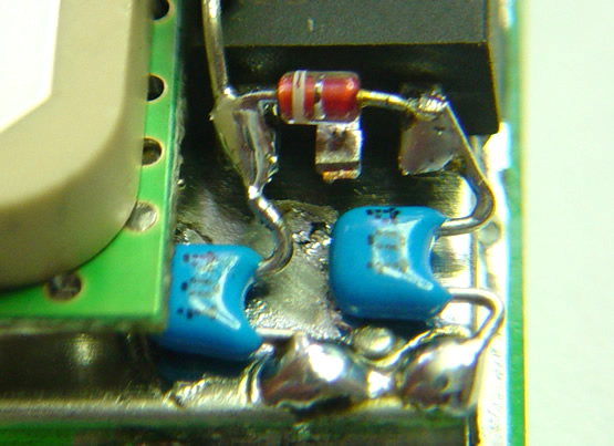
A pair of decoupling capacitors are added from the input to ground, and the output to ground. Generally, any value around 0.1 uF to 1uF or 10uF can be fitted, the only restrictions are the space to fit them and NOT to use electrolytics, as they don't bypass RF very well due to their internal inductance. In this case, I used 0.1uF monolithic capacitors, as that was all I had to hand. 1uF would have been preferable if available and if they would fit.
Here, the red wire is connected from the 7805 5V output to a pad on the GPS which is it's 5 volt supply rail. As the plug from the USB cable contained a 5 volt supply pin, it was fairly easy to locate a handy pad which connected to it, and use it for 5V supply injection. A 1N4004 rectifier diode is soldered to the input of the 7805, this helps protect things in case someone accidently connects a reversed polarity supply to the GPS cable.
Another view showing transistor, pullup resistor, 7805, diodes, bypass capacitors, and red 5V link.
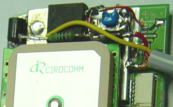
Here the cable to the TinyTrak is attached, the red wire for positive supply, the yellow for RS232 data, and the cable shield is used for ground return. A convenient and solid place to solder the wire shield is the edge of the metal shield covering some of the GPS electronics.
A shot of me hard at work at Harry's workbench, taken by Harry somewhat surreptitiously.
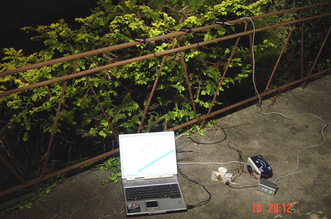
Outside, we set up Harry's laptop, the 3 GPSs, and a couple of TinyTrak boards (little green and blue LEDs are visible), and then the outside sensor light turned off just as the photo was taken...
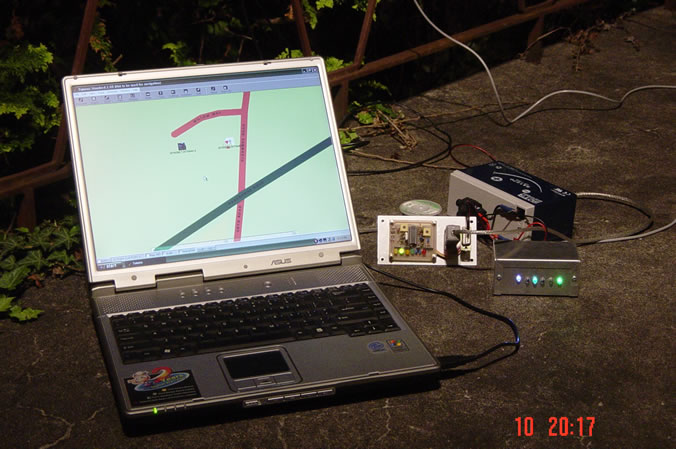
Now, with the sensor light switched back on, is the laptop with Harry's GPS plugged in the USB port, running TUMONZ mapping program, and the two other modified GPSs feeding data to TinyTrak PCBs running from a 12V Gel Cell.
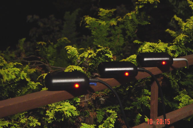
A closer shot of all three GPSs stuck to the patio handrail via the magnets inside the base of each GPS.
Another shot of the laptop, a TinyTrak test board of mine propped up against a solder reel, and the TinyTrak enclosed in a metal box that normally resides in my car.
Current U.S.A Server Time and Date
Current New Zealand Time and Date