This is the UK/USA version of the 11 element LFA by G0KSC and is not on his website at the moment.
Below are the dimensions for the 2 meter 144mhz UK/USA antenna as
designed by Justin G0KSC with some notes at the bottom. For more
detailed explanations and tips on construction techniques please visit
Justins website at G0KSC.
Antenna measurements:
> Element
Spacing Half element
length
>
> Ref
0 .5115
> DE1
.159 .4355 Feedpoint
> DE2
.322 .4355
> D1
.593 .4725
> D2
.974 .4445
> D3 1.362 .4525
> D4
2.024 .448
> D5
2.804 .4425
> D6 3.628 .4375
> D7 4.491 .4305
> D8
5.348 .423
> D9 6.182 .4195
Notes:
Please note the design
Frequency is for 144.300 MHz, see the Eznec file (see Justin’s page re: the
Eznec version). This antenna was designed around my requirements for a 144-145 MHz
version
"One big tip when tuning
these antennas is when adjusting the DE loops, adjust for a flat response
across the band you are going to use". Don't try and get the lowest SWR at
your chosen centre frequency as you will find the response across your band
will not be as desired.
Rather the way these antennas are tuned is to get a flat response which is
hopefully spot on or at a slightly lower frequency (e.g. 143.5 - 144.5), then
file each element down the exact same amount (0.25 mm at a time) to
get the desired band spread. Remember the higher the frequency the smaller the tolerance
for filling down. If you find the best "flat response" is higher
than your desired requirements, for example, between 145 - 146 MHz, then you will need to
re-cut all your elements again as they will be too short, unless this is your
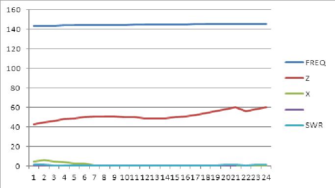
desired operating band. I cut my elements exactly as above and my original
frequency/impedance/SWR is as shown, "here".
G0KSC Note's:
All
elements are 3/8inch but DE1 and DE2 are 1/2 inch with 3/8 inch
ends
Ensure you use a 1:1 balun at the feedpoint, this could be a simple
choke balun (coiled coax) but my prefered is a grounded 'G0KSC' Pawsey
stub as this gives a DC ground to the loop. Read my Making a Balun notes.
|
 This link is for the Eznec files for this antenna. This link is for the Eznec files for this antenna.
I originaly did the bend angles too large and then had to flatten the
bends to achieve the correct height of 28mm as per the diagram.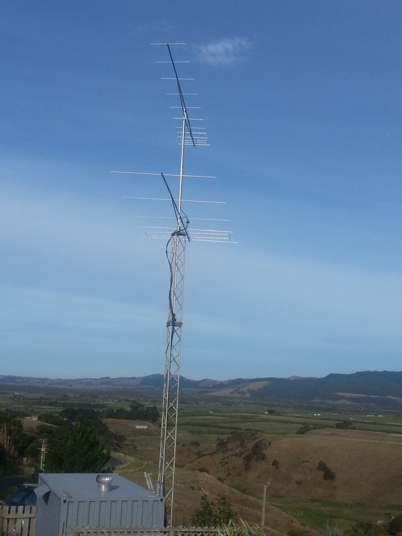
Please,
get the measurements as accurate as possible. Cutting elements
a little longer than you need and filing to size will result in a much
better antenna. A few hours more in the build phase will result in many
more year pleasurable useage of your antenna(s).
> DE1
and DE2 will have to be cut shorter than the above mentioned to
allow for the radius on the 3/8 inch tube. If they are cut a bit
short, no problem, the 3/8 can exit the 1/2 inch a little longer, just
adjust this loop for the best SWR upon completion.
This antenna is a new, unreleased design with a rear fed loop.
|