4 ELEMENTS VHF YAGI ANTENNA (144-146 MHz)
I Z33T home page I Z33T web pages in english I
EXCELLENT HOMEMADE 4 ELEMENTS YAGI ANTENNA FOR VHF, 144 - 146 MHz (originally designed by Martin, DK7ZB)
- Cheap, lightweight compact antenna which is easy to made.
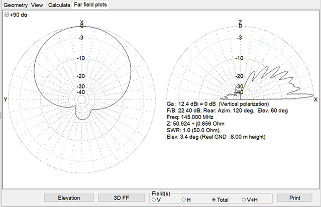
- Excellent performance, clean main diagram and very good Front/Back ratio.
- Gain = 8.25 dBi (6.1 dBd compared to dipole).
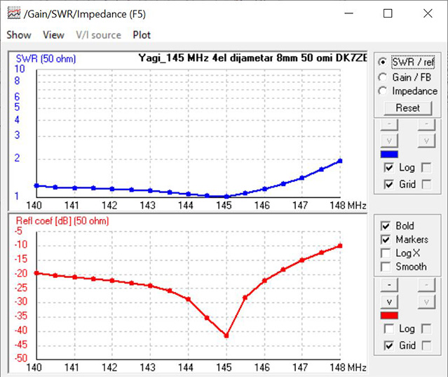
- Antenna has very low SWR across wide frequency range, so it is very easy to replicate without big errors even if the dimmensions are not exactly acurate.
- Coaxial cable (50 ohm) is connected directly to the driven element.
Antenna length is only 79 cm.
All elements are made from 8 mm diameter aluminum tubes. Material can bi find in every hardware store.
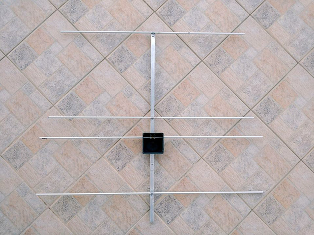
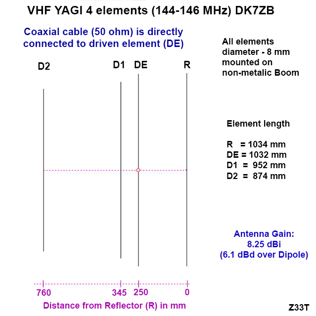
The boom should be non-metalic. If metal boom is used, the elements length sould be corected because of conducting boom, so the elements should be few milimetar longer, depending of boom diameter and distance between the antenna elements and conductive boom.
I have used metalic (aluminum) boom and the elements are welded on the top of the aluminum quadratic profile 15x15mm, so all elements length are 4 mm longer than dimensions on the picture obove and antenna model in antenna modeling software due to boom correction (BC)
The impedance of the antenna is 50 ohms, so a 50-ohm coaxial cable can be connected directly.
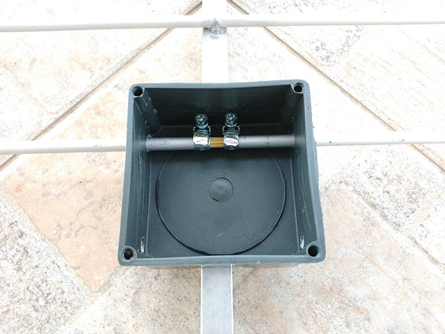
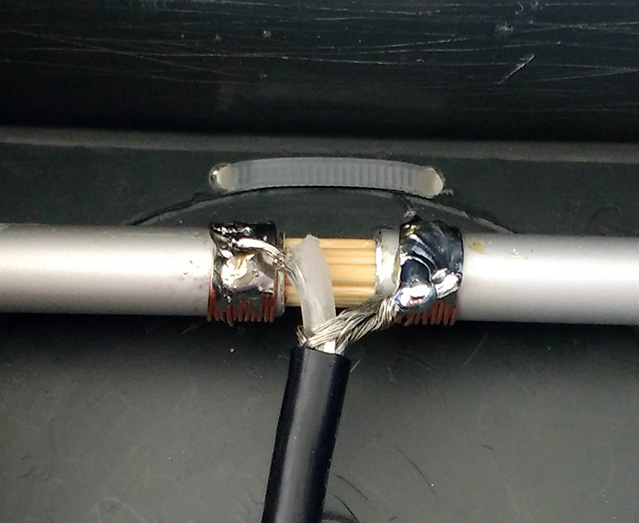
First I thought of connecting the coaxial cable to the dipole by mounting metal clamps, tinned them and soldered the coaxial cable to them. According to the measurements, the lowest SWR I could achieve was 1: 1.5 in the middle of the band (145 MHz), and at the ends of 144 and 146 MHz, the SWR was even higher, SWR = 1: 1.8 which is not good.
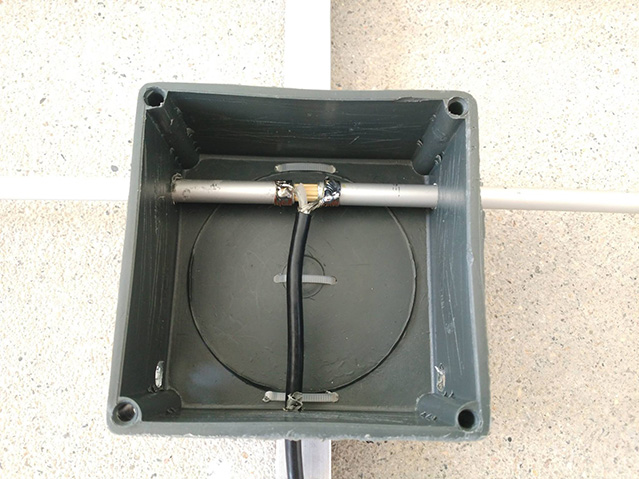
After that, instead of metal clamps that had a large surface area and added additional capacity to the dipole, I wound several coils of uninsulated copper wire tightly at the ends of the aluminum tubes where the coaxial cable was to be connected, tightened it by bending the ends, and tinned it. Then I soldered the coaxial cable with very short leads. Now the SWR was great. 1: 1.1 across the entire 144-146 MHz band! I hope this will be a nice lesson for those who will try to make a Yagi-antenna.
The antenna front-to-back radio is very good. Fo example, If I receive a signal with S-8 according to the S-meter, when I turn the antenna opposite from the signal source, it can barely be noticed that there is a signal!
The antenna is small and easy to make. It has real 6 dBd gain over the dipole and I recommend it to anyone who wants to have a great little Yagi antenna for the 2 meter band.
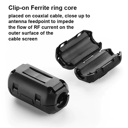
It is good to make a 1:1 balun for connected asymetric coaxial cable to symetric antenna feed, but I did not, because I am satisfied with the results even without balun. Just using the clip-on ferrite ring core on coaxial cable near the driven element feedpoint:
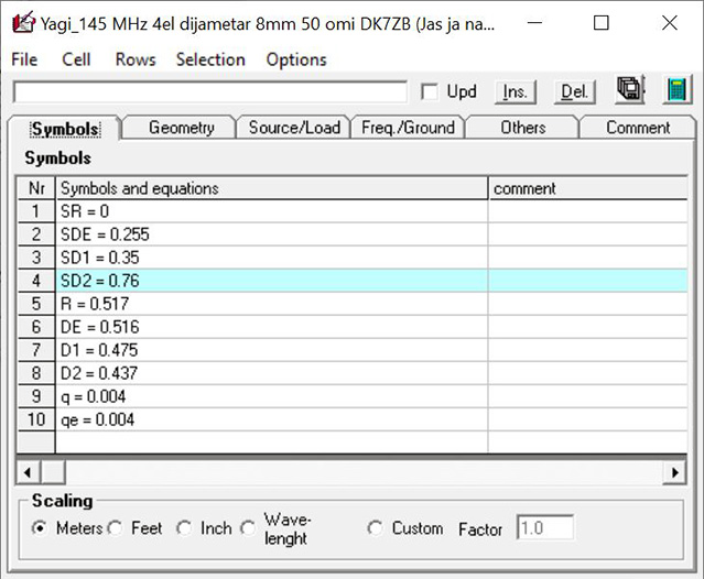
Antenna elements definition in the MMANA-GAL antenna modeling software:
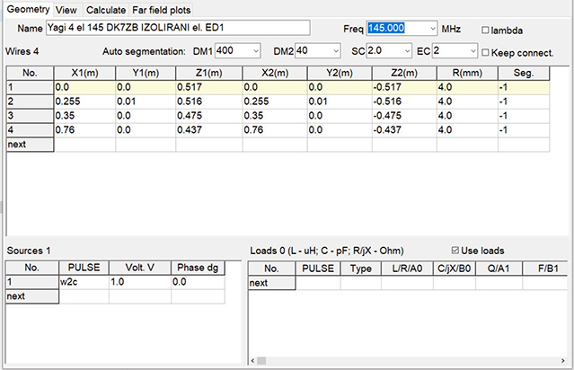
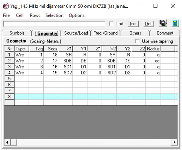
Antenna elements definition in the 4nec2 antenna modeling software:
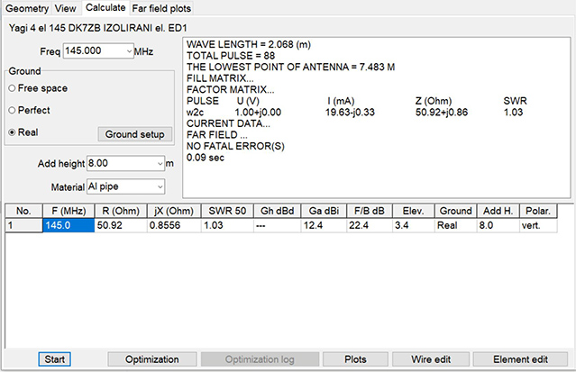
SWR and frequency bandwidth of the antenna:
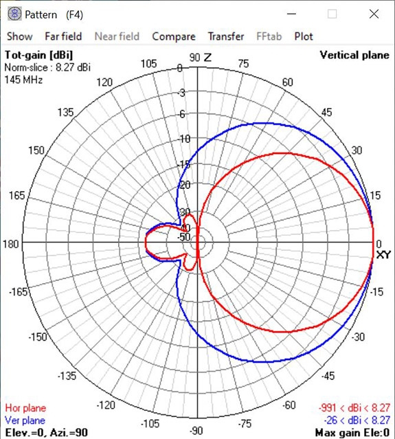
Antenna radiation diagram in Horizontal and Vertical plane:
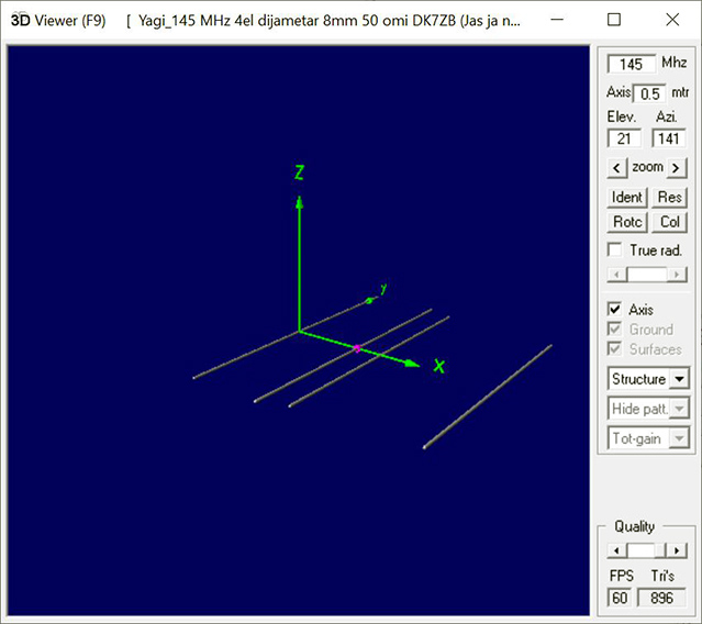
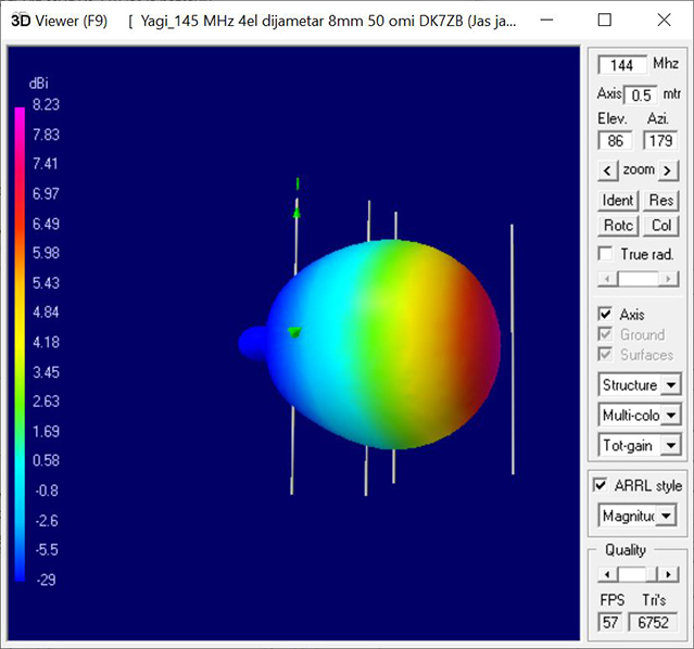
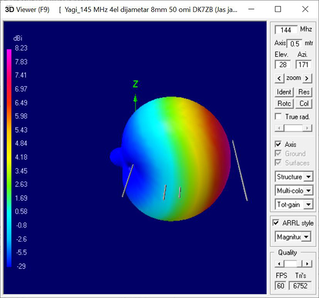
3D Radiation Pattern:


This antenna is originally designed by Martin, DK7ZB and can bee seen here.
- - - - - - - - - - - - - - - - - - - - - -
Mile Kokotov (2020)
Mile Kokotov, M.Sc. is industrial engineer manager and has a master`s degree in technical science with almost 40 years expirience in RF-technology.
Feel free to visit other articles and projects on his website
I Z33T home page I Z33T web pages in english I