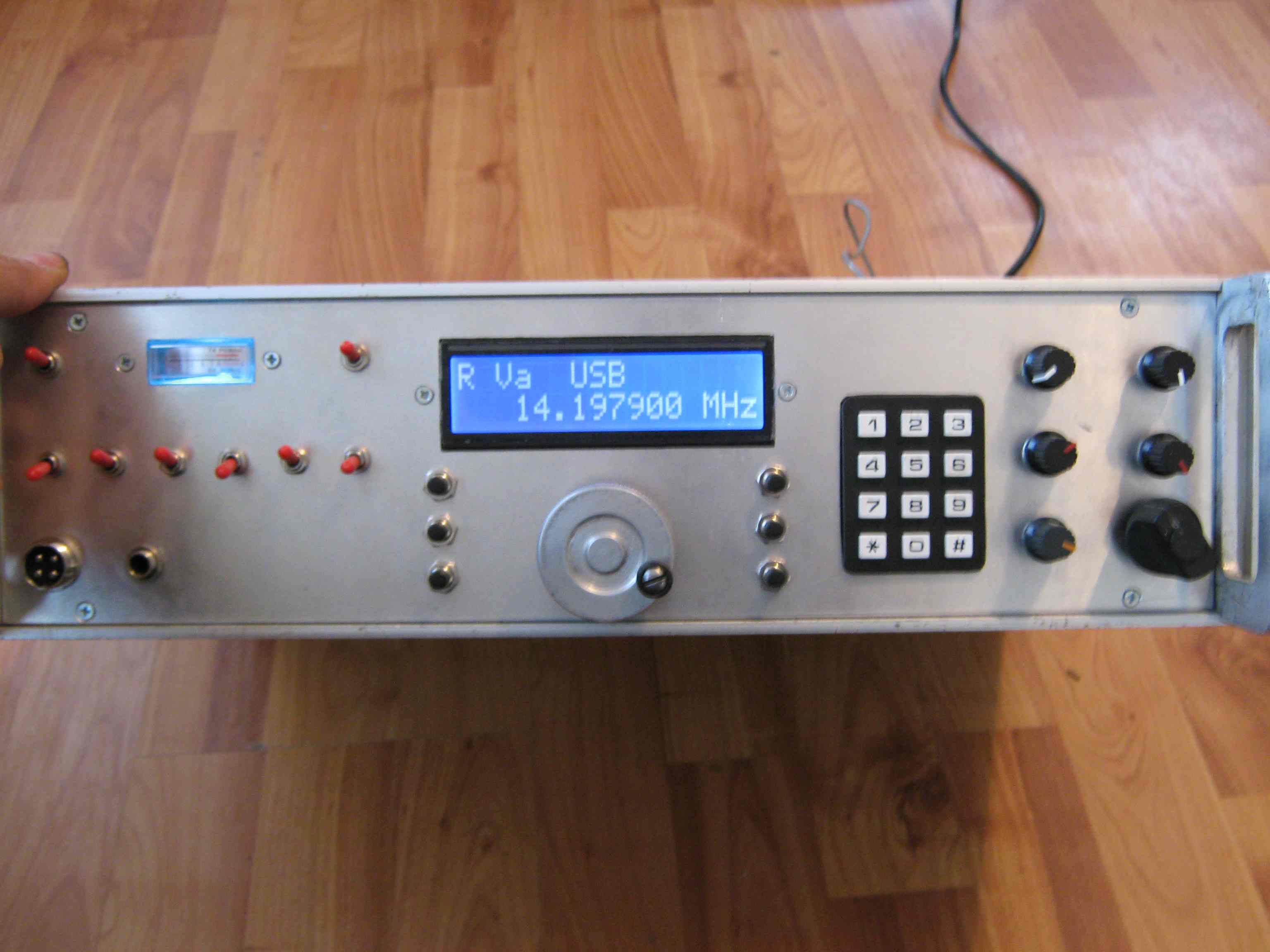
DDS HF TRANSCEIVER SSB/CW |
This SSB/CW transceiver covers the 160 m to 10 m amateur radio bands. A VU3CNS DDS module based on the AD9850/AD9851 provides frequency generation with satisfactory performance. Some spurious signals may be present above the 14 MHz band.
To minimize phase noise, the DDS is driven by an external 150 MHz oscillator, with the internal PLL of the AD9851 disabled. For optimal performance, both the DDS board and LCD module should be properly shielded.
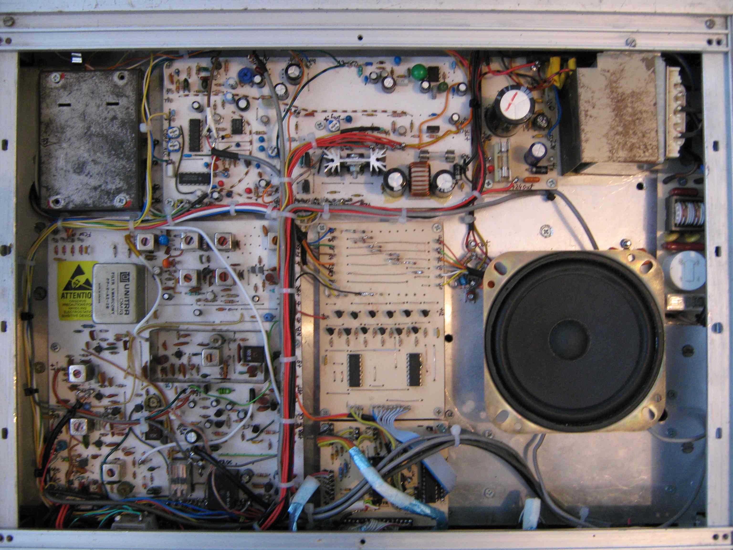
The receiver uses a single 9 MHz intermediate frequency (IF). SSB filtering is provided by a vintage Unitra crystal filter, while an additional narrow filter can be installed for CW operation. The receiver architecture is similar to that of the Kenwood TS series.
A 2N5109 amplifier stage improves performance on the higher bands. An MFJ audio filter offering HPF, LPF, BPF, and notch functions further enhances receive selectivity. The receiver delivers good overall performance with a low noise figure, thanks to its RF MOSFET stages and diode-based double-sideband detector.
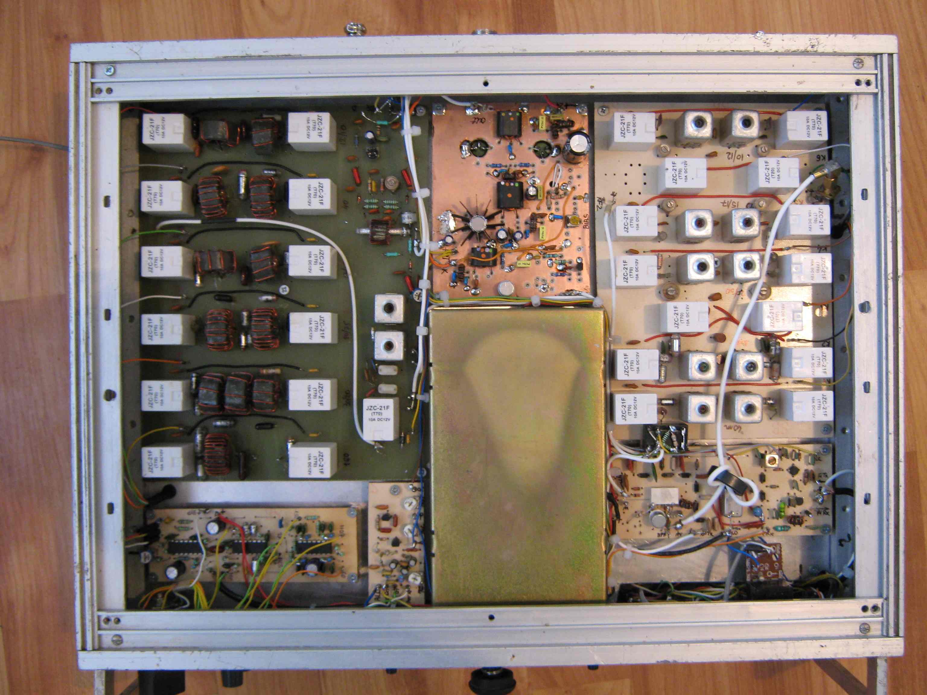
Elecraft K2 band-pass filters are used for both receive and transmit paths. These filters were selected because they are easy to align and adjust. DL7MAJ has published several modifications to the original Elecraft K2 filter design; refer to the download section for details. All relays are controlled by the VU3CNS microcontroller.
The transmitter produces approximately 10 W of output power using a pair of 2N3375 transistors. For 12 V operation, higher-performance output transistors are recommended. An audio limiter/compressor is included in the transmit audio chain to improve average transmitted signal strength.
DOWNLOAD
![]() HF DDS SSB/CW Schematic Diagram
HF DDS SSB/CW Schematic Diagram
![]() AD9851 DDS modified
AD9851 DDS modified
![]() Other informations about DDS: Link VU3CNS DDS.
Other informations about DDS: Link VU3CNS DDS.
![]() Audio Filter CW/SSB MFJ-722
Audio Filter CW/SSB MFJ-722
![]() Band Pass Filter Elecraft K2 modified by DL7MAJ
Band Pass Filter Elecraft K2 modified by DL7MAJ
![]() Improved ALC circuit with LM3900
Improved ALC circuit with LM3900
GALLERY