PLL DRO 12.4775GHz (rev. eng.) |
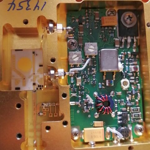
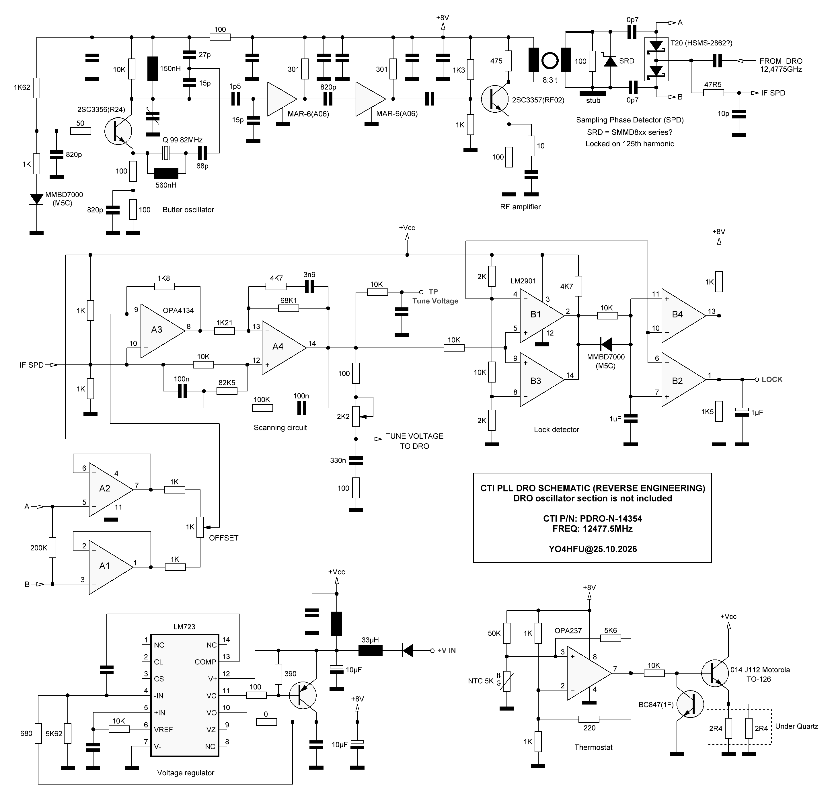
Reverse-engineering schematic of a PLL DRO (PLDRO) module recovered from a NORTEL 24GHz ODU. The DRO oscillator itself is not included, it is a wire-bonded assembly.
The circuit is particulary interesting because it demonstates a PLL implementation based on Sampling Phase Detector (SPD) combined with a Step Recovery Diode (SRD) harmonic generator.
The resulting IF signal, carrying the phase error information, is amplified and filtered through a LPF. A dedicated search/acquisition circuit assists in initially locking the DRO to the nearest frequency corresponding to an integer multiple of the reference quartz oscillator.
The schematic is useful as a reference for potential operating frequency modifications, connecting an external reference source, or adapting the PLL to a DRO oscillator (which would require varicap tuning control).
CTI PN: PDRO-N-14354
FREQ: 12.4775GHz

 PDRO CTI schematic
Internal photos
Understanding Phase-Locked DRO Design Aspects - Avil Brillant