FT847 Improvements |
02.2019
#1. Improvement of DSP spurious "noise".
#2. Improvement of TX "in band" spurious
#3. Improvement of TX "out band" spurious.
#4. Improvement of frequency stability vs. temperature variation.
#5. Improvement of RX noise figure and IP3 for 144MHz
1#. 144MHz RX spurious noise due to poor GND connection of DSP board
![]()
![]() Improvement of DSP spurious emission
Improvement of DSP spurious emission
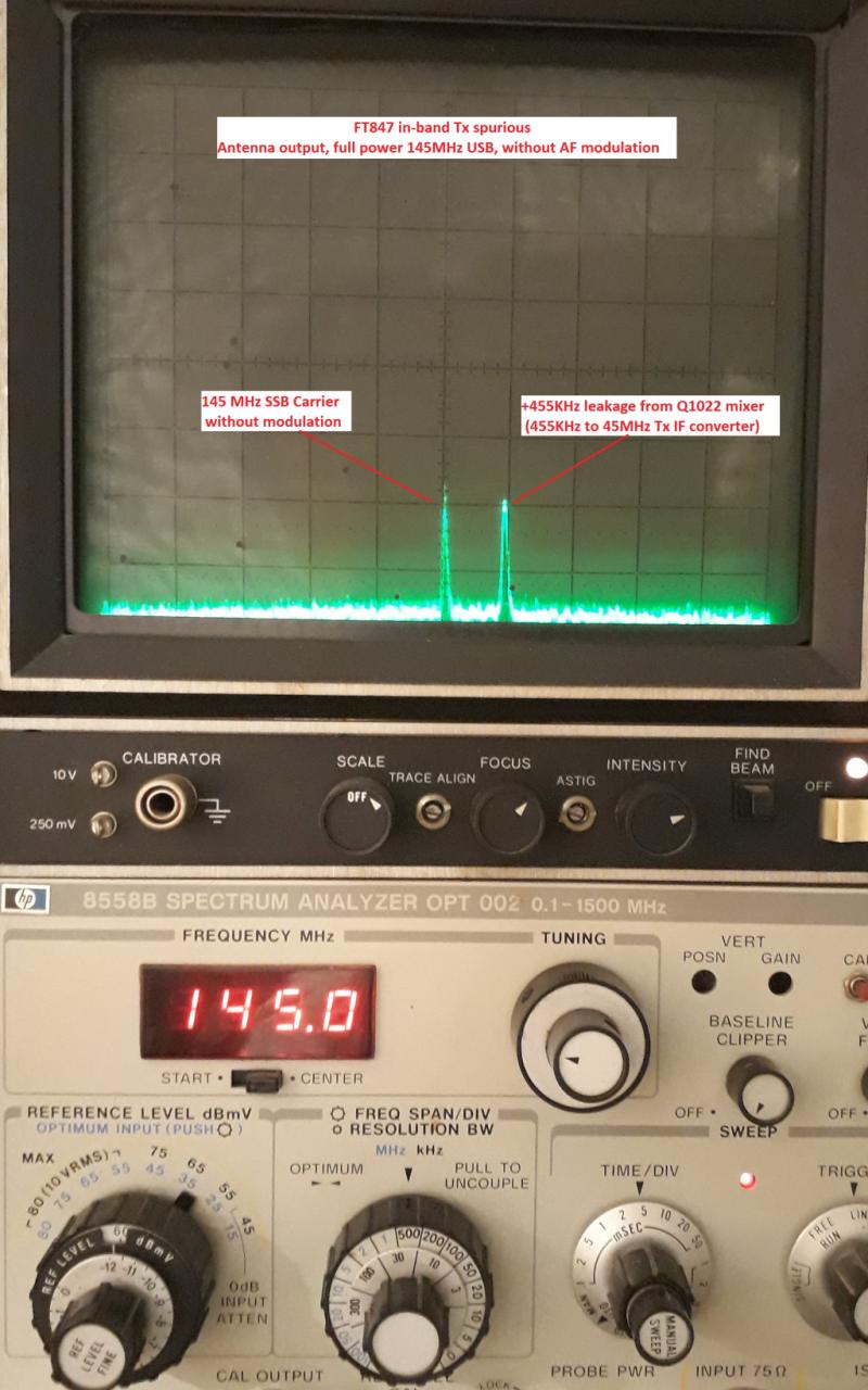
#2. TX "in band" spurious
During transmitting, 455KHz/45.580MHz converter has leakage and 2nd LO can be easy observed at antenna output.
Below you can see 145MHz SSB residual carrier without modulation (AF MIC at minimum level). Also Ftx+455KHz not modulated carrier appears due to poor shielding of TX IF chain. This spurious can be easy find by other receiver tuned with +455KHz up. Example: FT847 TX tuned at 144.300MHz, spurious signal can be find at 144.755MHz using an hand held FM receiver.
Any TX spurious signal can be problematic in case of QRO usage, the spurious level can be enough boosted in order to disturb other communication.
![]()
![]() Spectrum analyzer at 145MHz, FT847 not modified
Spectrum analyzer at 145MHz, FT847 not modified
![]() Shield installed between 45MHz crystal filter and mixer
Shield installed between 45MHz crystal filter and mixer
![]() Spectrum analyzer +10dB more sensitive, no more in-band spurious, only noise floor of TX chain
Spectrum analyzer +10dB more sensitive, no more in-band spurious, only noise floor of TX chain
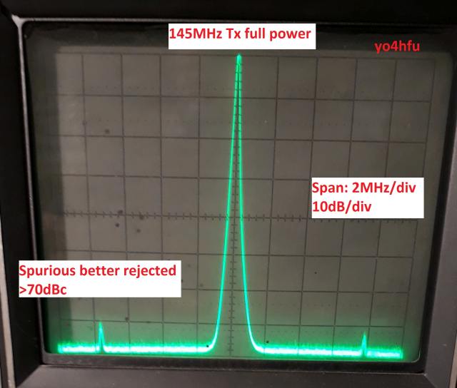
#3. Improvement of TX "out band" spurious
Poor rejection of TX mixer products on VHF due to bandpass filter T3005/T3008/T3010. Some improvements can be done if selectivity of band pass filter is increased. Capacitors C3125 (2p) and C3089 (15pF) were replaced with smaller values. If values are decreased too much, 144MHz full power (50W) will be affected by insertion loss. After modification out-band spuriours are 7dBc better attenuated (TX@145MHz).
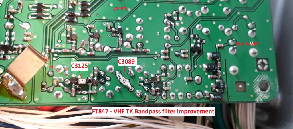
New capacitor value: C3089 8,2pF and C3125 1,2pF. Both capacitors are located on RF board bottom layer.
![]()
![]() Spurious signals before modification
Spurious signals before modification
![]() Spurious signals after modification
Spurious signals after modification
![]() Location of band pass filter capacitors
Location of band pass filter capacitors
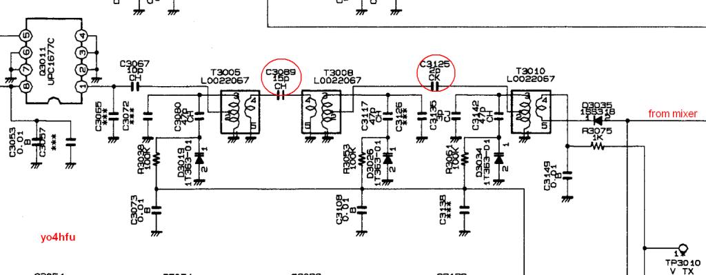
![]() VHF Tx band pass filter schematic
VHF Tx band pass filter schematic
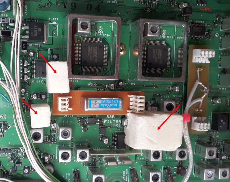
4#. Improvement of frequency stability versus temperature variation
Next quartz crystals were insulated with foam: Main Reference X1001, BFO DDS X1003, FM carrier modulator X1002.
Future upgrade: I intend to replace 22,625MHz main oscillator by TCXO-9 Yaesu option designed for FT-817/857/897.
![]()
![]() View of foam insulation
View of foam insulation
#5. Improvement of RX noise figure and IP3 for 144MHz
Below are my measurement for 144MHz original front-end. Spectrum analyzer was connected instead of 1st mixer.
![]() 2 tone generators connected to VHF Antenna, 100KHz spacing, level 2 x -34dbm
2 tone generators connected to VHF Antenna, 100KHz spacing, level 2 x -34dbm
Preamplifier OFF
Front-end gain: 12,1dB
OIP3: 1dBm
IIP3: -11.9dBm
NF: 5.5dB
Preamplifier ON
Gain of Norton Internal Preamplifier: 8.5dB
Front-end gain: 21.4dB
OIP3: 1.5dBm
IIP3: -19.9dBm
NF: 4.5dB
Above measurements are similar with DF9IC results.
![]() 2 tone generators connected to RF Board (no Rx/Tx PIN Switch), 100KHz spacing, level 2 x -34dbm
2 tone generators connected to RF Board (no Rx/Tx PIN Switch), 100KHz spacing, level 2 x -34dbm
Preamplifier OFF
Front-end gain: 12,5dB
NF: 4.8dB
Preamplifier ON
Front-end gain: 22,3dB
NF: 2.8dB !
Conclusion:
- Poor IP3 capability of FT847 for 2m band. Original front end (preamplifier and amplifier) is the main source for intermodulation.
- During measurements was observed poor IP3 of band pass filters!!! These small ferrite core coils can generates IMD and are not suitable for a high IP3 receiver.
- Noise figure is too high for an GaAs MOSFET device. Why Yaesu (not only Yaesu) use low noise amplifier after high loss input filter?! The noise figure will be degraded forever and GaAs performance is lost!
- NF of internal preamplifier is better without antenna PIN switch, that means PIN switch and VHF low pass filter have 1-1.5dB insertion loss! RX signal is degraded before to be amplified. Don't try to replace your coaxial feeder, better to replace the transceiver or use tower LNA...hi (if you need better NF).
It is enough to have a good quality amplifier in front of mixer?
Next step I have proceed to measure IIP3 of 1st mixer (GN2011 - Panasonic GaAs N channel).
![]() 1st Mixer IIP3, isolated and tested, 100KHz tone spacing:
1st Mixer IIP3, isolated and tested, 100KHz tone spacing:
OIP3: 11,5dBm
IIP3: 14,5dBm
Loss: -3dB (see datasheet, GN2011 has small conversion loss)
According my measurements, IP3 of mixer is not very high. Maybe the IP3 value is better and my measurement is not very accurate. IP3 measurement of mixer can be affected by many factors.
IP3 can be improved using an attenuator in front of mixer input, not very high attenuation, otherwise NF will be degraded. We will see during final measurement.
My idea is to replace entire VHF-H front end using low noise, high IP3 MMIC, air coils and low loss band pass filter for input. Also antenna PIN switch will replaced with relay and the switching between original/modified front end will made using small relays controlled by "ATT" keypad button. The new frontend can be activated only on VHF High Band 140-174MHz. All other functions of FT847 are not affected. "ATT" attenuator function is not affected on other bands.
Update: 18.12.2018
After few days of experiments I manage to design the new front end. Because the space is limited, it is not possible to use high Q resonators in order to achieve low loss and sharp selectivity. The most difficult is to keep low loss insertion in front of first stage. Using a double cell BPF in front of PGA103, the NF was strong affected by insertion loss and mismatched.
The BPF was tested alone and insertion loss was found 0.5dB, but NF has increased from 0.65dB to 2.4dB! I try several matching tehniques without significant improvment. The IIP3 of PGA103 is very good but I like to use some filtering between antenna and first stage. It is good to reject strong signal: FM broadcasting, GSM, airplains, DVBT, etc. My input filter solution is to use 2 cascaded filters, 3rd order LC low pass filter and other one high pass filter. Global selectivity is not very narrow, but NF is not degraded. The main filtering is located between first amplifier and double balanced mixer.
Let's see the schematic diagram:
![]() New Front end Schematic
New Front end Schematic
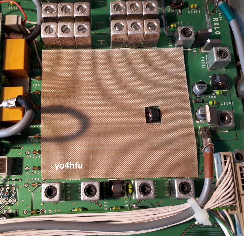
![]() Front end location
Front end location
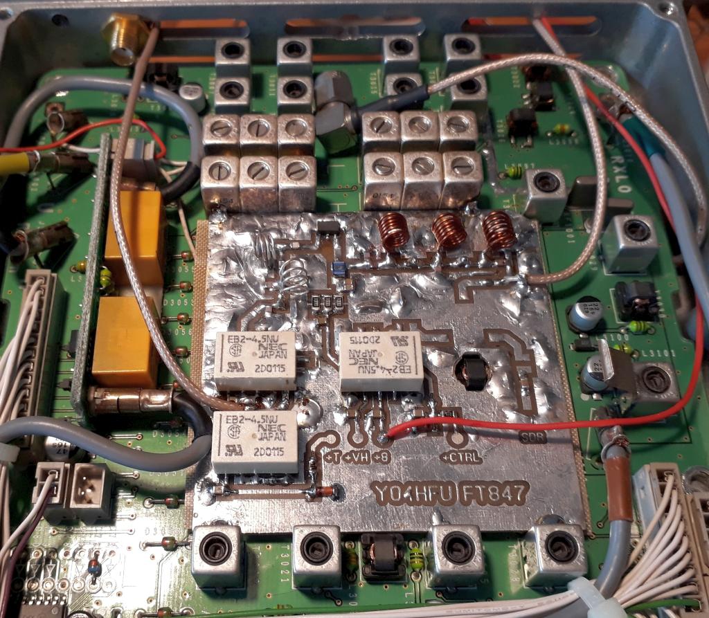
![]() Front end PCB vers.1 during testing
Front end PCB vers.1 during testing
After several measurements before/after mixer and at the IF RX output (45MHz), no big improvement was observed between original and new front end, even if the IP3 of PGA103 was excellent (IIP3=+10dBm). After IP3 simulation using AppCAD[Noise Calc] software, the final conclusion was poor IP3 performance of FT847 mixer. The simulation reveals low IIP3 compared with my previously measurements. Next day I start to dig more deep in order to understand why IIP3 improvement is only 3dB and why mixer hasn't good performance.
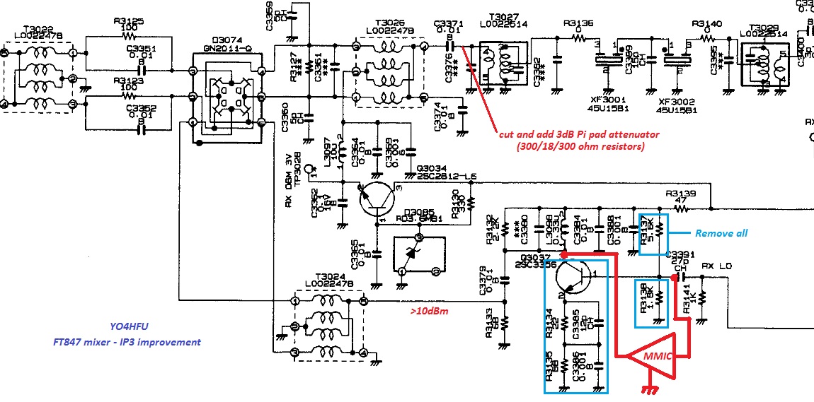
One explanation is measurement condition, the mixer was isolated during IP3 measurement and RF/IF ports were well terminated by 50 ohms. On the main PCB the mixer is not correctly matched. It is clear to see how port IF is connected directly to first 45MHz quartz filter! Big mistake because any filter and special the quartz filter have high return loss outside of pass band. The mixer IP3 will be affected if port IF is not broadband terminated. We can use a diplexer (low loss) or pad attenuator between mixer and quartz filter. Diplexer solution is very nice but the space is not enough. So I choose 3dB resistive pad. No big improvement using higher value. After IF port modification the result was better but not enough for my taste.
Next question was the level of LO drive. The level of LO was found +2dBm (high side injection LO=190MHz). Using external signal generator, LO signal was injected straight to mixer. If the level is more than +10dBm, the results are very good. Broadband amplifier Q3037 is replaced by SNA-586 MMIC. Any other similar MMIC device can be used. Output level is +15dBm.
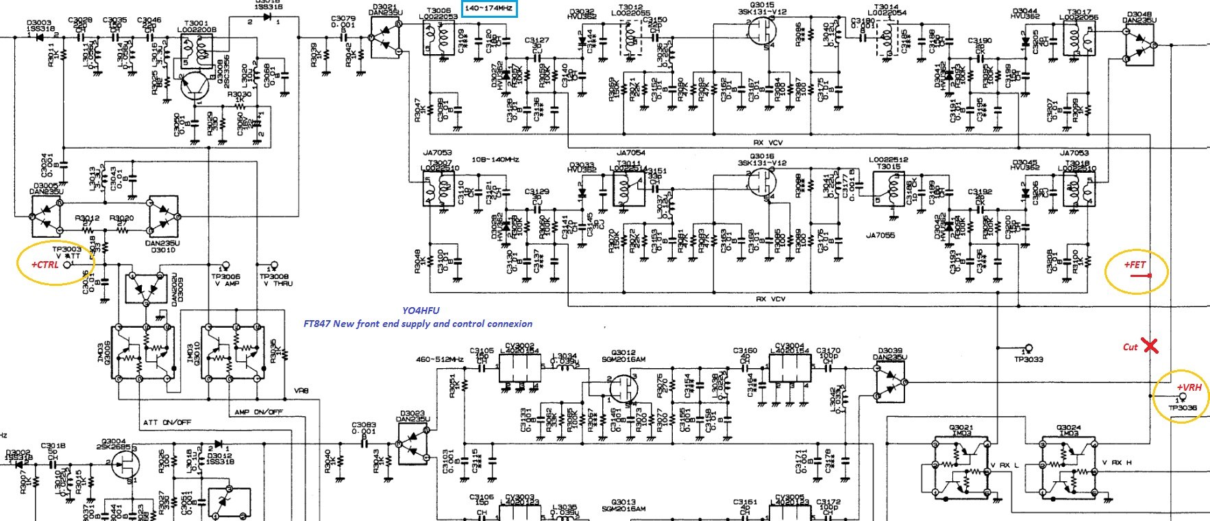
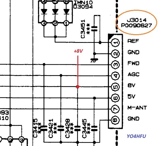
New front end interconnection with FT847 RX Mixer
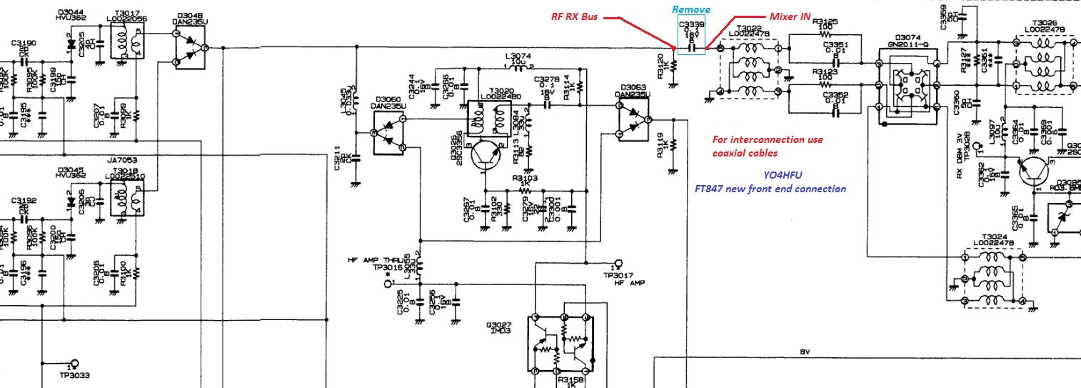
New front end interconnection, power supply and control from FT847 RF board
Conclusion:
New IIP3 value is around +3dBm, instead of -19dBm obtained by original front end. Noise figure is better than 0.8dB, instead of 4.8dB (2.8dB Preamp ON). The receiver is quiet, more easy to copy weak signals. New front end bandwidth is 5,5MHz/-3dB. Auxiliary RF output is active if "ATT" is engaged and can be used for an external 144MHz SDR.
PCB final version not ready; maybe other test using Mini-Circuits DBM +13 or +17dBm level, INRAD roofing filter upgrade.
LE: SYM-18H (level 17dBm) was tested without significant improvement of IP3. Inrad filter is under construction.
![]()
![]() FT847 Service Manual
FT847 Service Manual
![]() FT847 Technical Supplement
FT847 Technical Supplement
![]() FT847 High resolution schematics (.bmp)
FT847 High resolution schematics (.bmp)
![]() FT847 Operating Manual
FT847 Operating Manual
![]() DIY Standby cable for QRO control (PS2 cable modification)
DIY Standby cable for QRO control (PS2 cable modification)