IF/Controller for 24GHz WAVELAB |
In order to reuse 23GHz Wavelab for 24GHz ham radio band, suitable power supply, LO and 2nd frequency conversion to 144/432 are required. Next project can solve this issue, it is not the most simple design but a different approach.
Features of Wavelab IF Conversion/Controller:
- low phase noise PLL for LO1 and LO2 using fractional PLL MAX2871, 125MHz phase detector reference
- good frequency stability controlled by 10MHz OCXO and low noise 125MHz ADF4001 PLL reference
- monitoring of output power, internal temperature, 12V power supply voltage. LED bargraph indication or/and I2C 2x16 LCD. Power peak hold indication.
- PA TX voltage selection 6V (2Wout) and 7,5V (4Wout), -5V bias interlock
- antenna relay sequencer, RF/DC VOX, manual PTT, optional external fan control
- low heat dissipation using switched mode voltage regulators and LDOs
- selectable IF 144MHz, 145MHz, 432MHz or 433MHz coresponding with 24.048GHz
- no tune RF chain using 2350MHz SAW filters and cheap 2.4GHz ICs
- PLLs unlock indication (on LCD or flashing LED bargraph)
- future upgrade to support Wavelab XN transverter (splitted RX/TX IF)
Update 06.06.2023: Spurious response (+/- 20MHz) noticed if PA voltage is increased from 6V to 7.5V. It is visible during SSB modulation test.
Enclosure: Hammond 1444-753 / 1434-12 (178 x 127 x 76mm)
Fuse bits
Atmega328P: low_fuses=0xE2; high_fuses=0xD6; extended_fuses=0xFD; 8MHz internal
Attiny84: default; 1MHz internal
![]()
![]() Schematic IF/Controller Wavelab
Schematic IF/Controller Wavelab
![]() PSU PCB gerber files
PSU PCB gerber files
![]() IF PCB gerber files
IF PCB gerber files
![]() Atmega328 firmware v1 - I2C LCD or LED indication, temperature reading on LCD, FAN control, LCD I2C address 0x27
Atmega328 firmware v1 - I2C LCD or LED indication, temperature reading on LCD, FAN control, LCD I2C address 0x27
![]() Atmega328 firmware v2 - I2C LCD disabled, only LED indication, LED voltage battery indication during RX (temperature resistors used to adjust span), temperature disabled, FAN disabled
Atmega328 firmware v2 - I2C LCD disabled, only LED indication, LED voltage battery indication during RX (temperature resistors used to adjust span), temperature disabled, FAN disabled
![]() Attiny84 firmware v3 - 144/432, Wavelab XP supported, LO1 3616MHz
Attiny84 firmware v3 - 144/432, Wavelab XP supported, LO1 3616MHz
![]() Wavelab internal modification to reduce RX consumption
Wavelab internal modification to reduce RX consumption
![]()
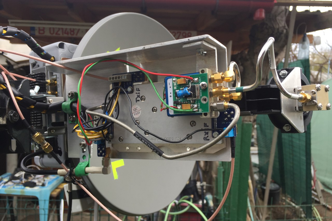
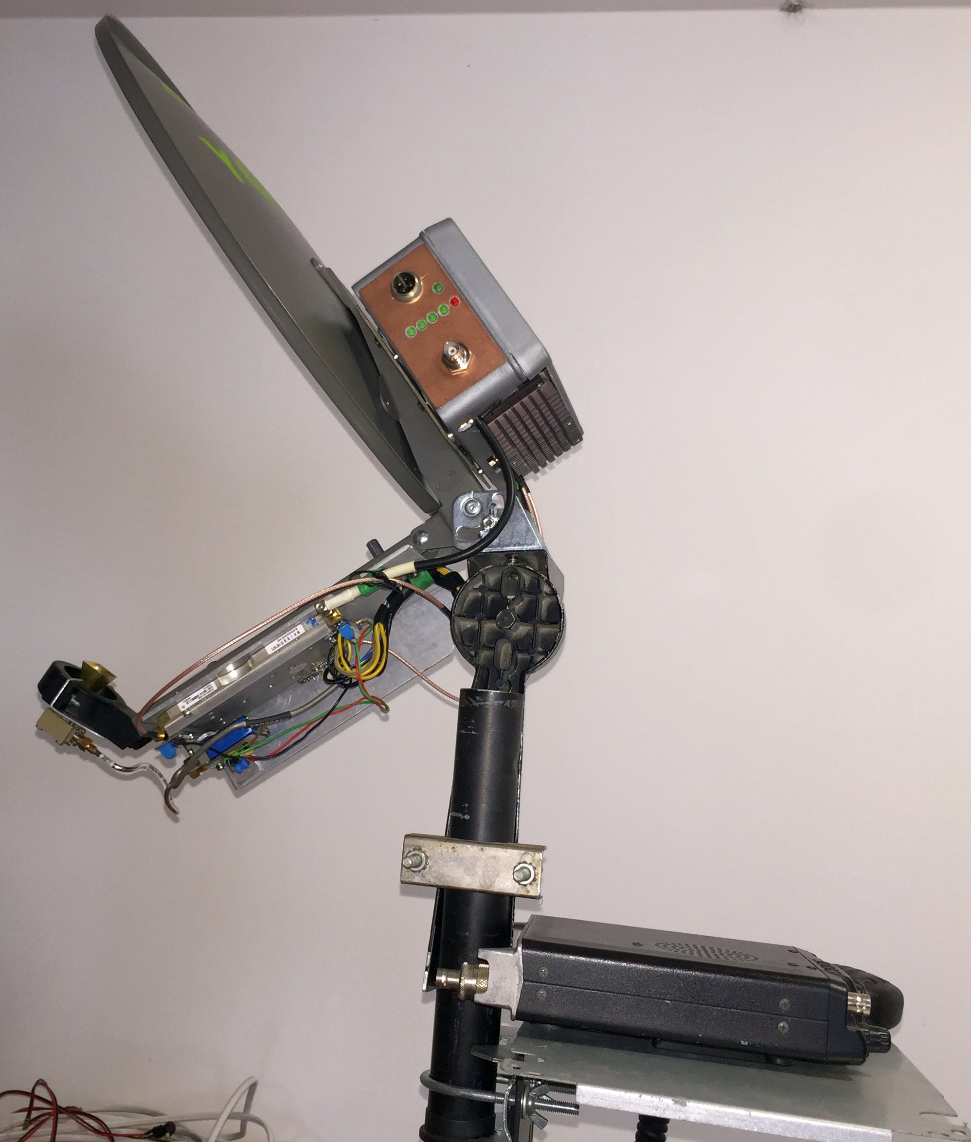
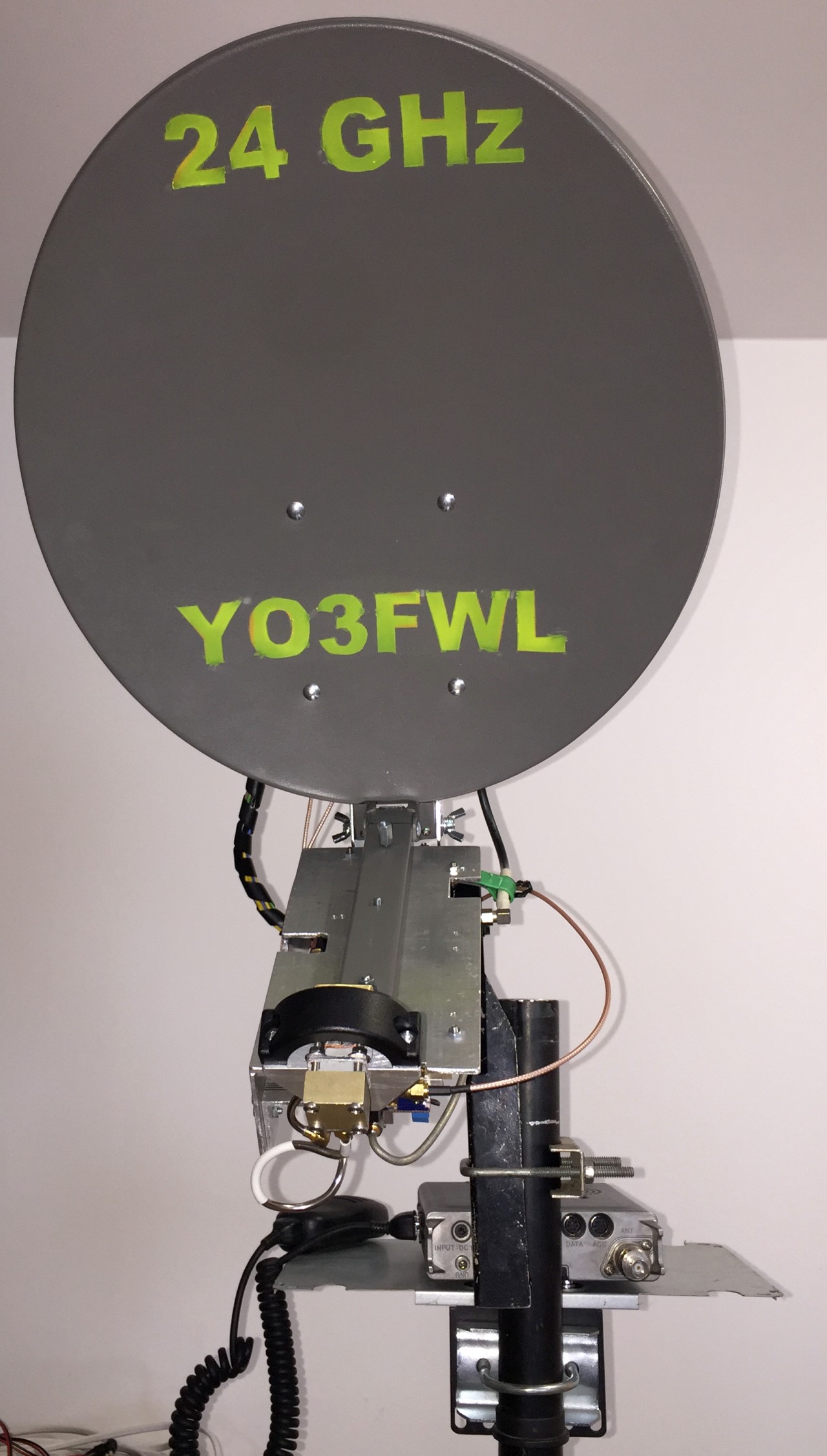
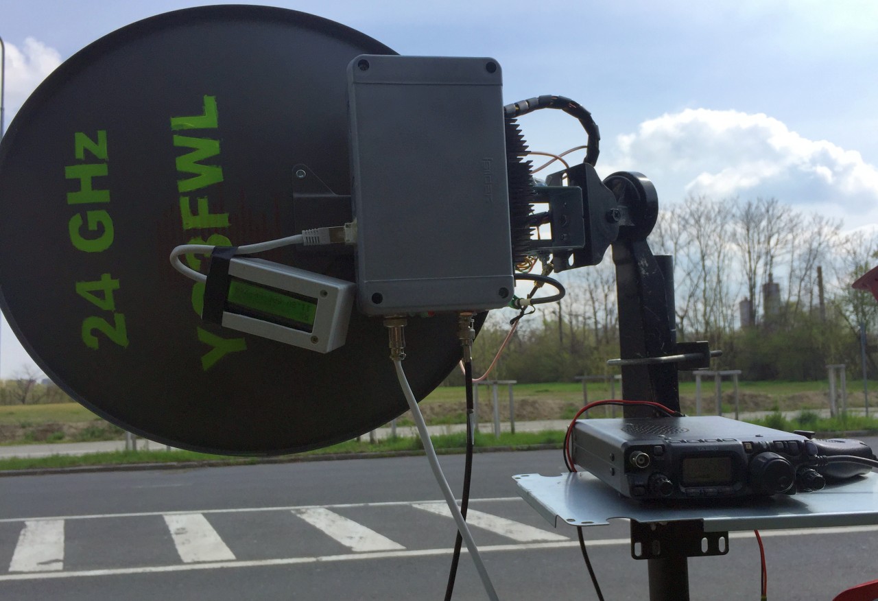
Method of assembly approached by Cristi YO3FWL. Good results achieved:
>>Photo 1<<, >>Photo 2<<, >>Photo 3<<, >>Photo 4<<, >>Photo 5<<
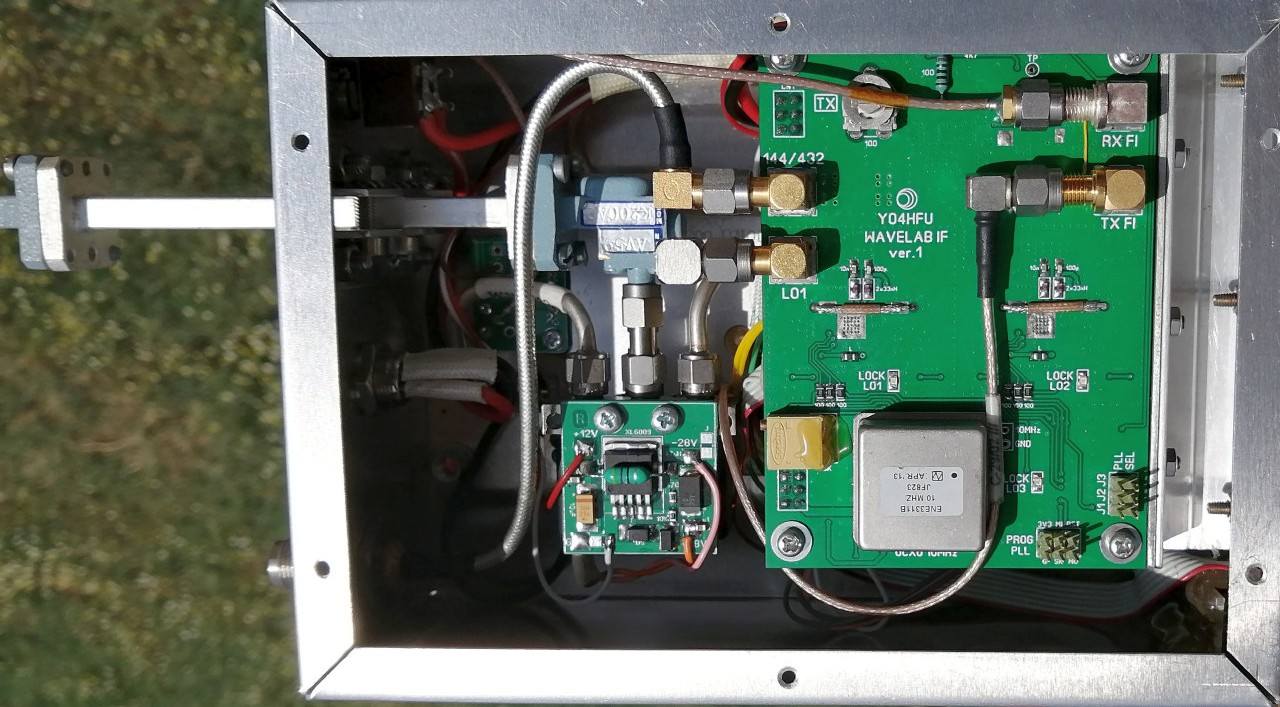
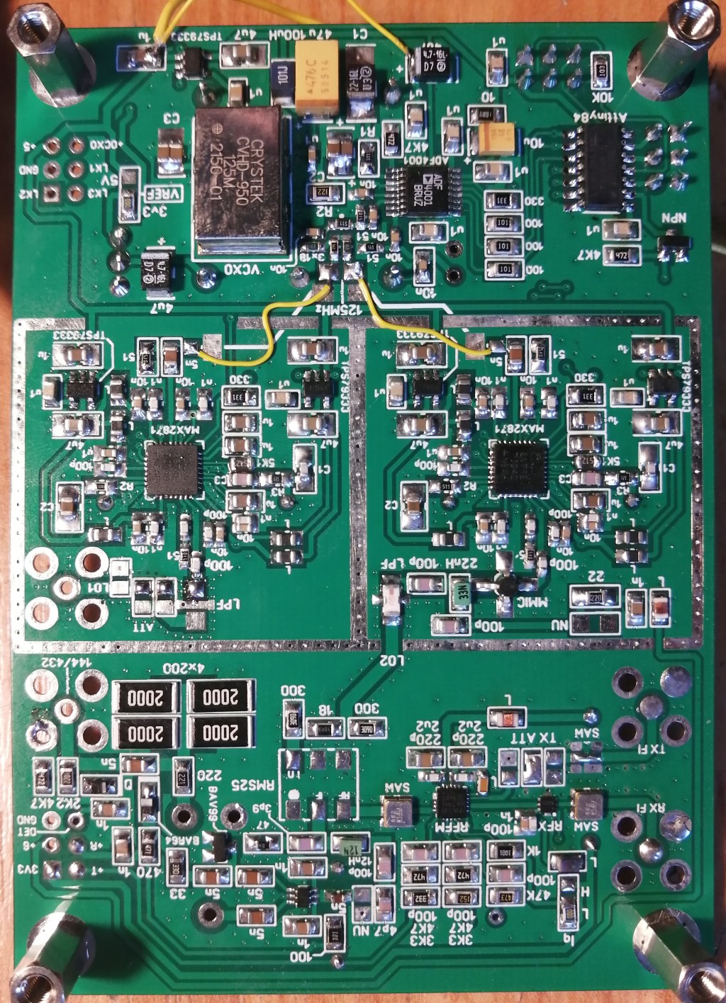
![]() IF Wavelab PCB view during testing
IF Wavelab PCB view during testing
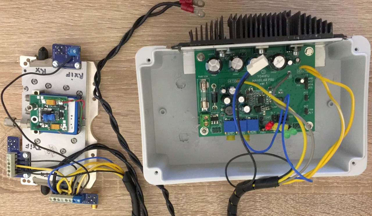
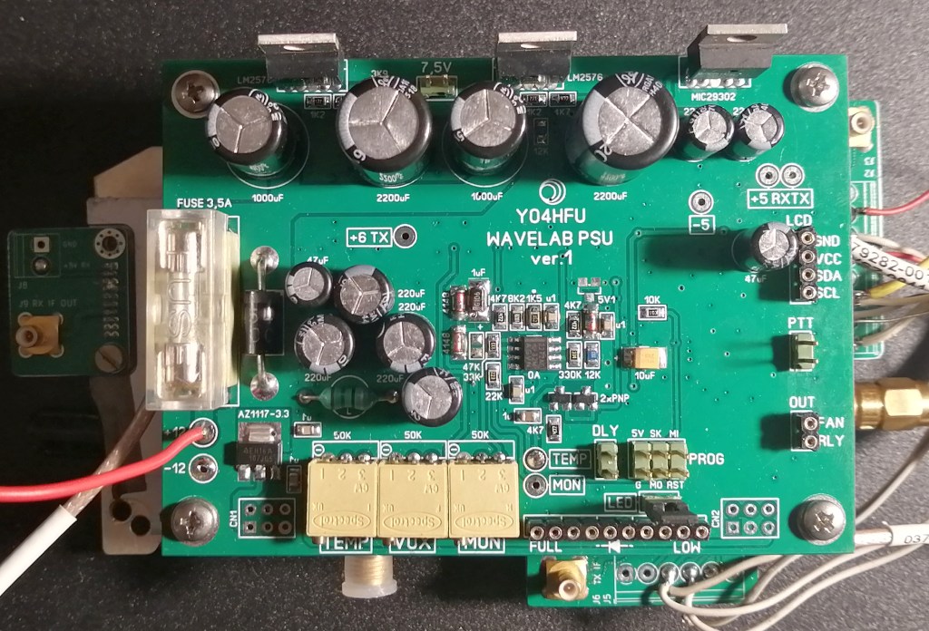
![]() PSU Wavelab PCB view during testing
PSU Wavelab PCB view during testing