ADF41513 microwave prescaler by 100/1000 |
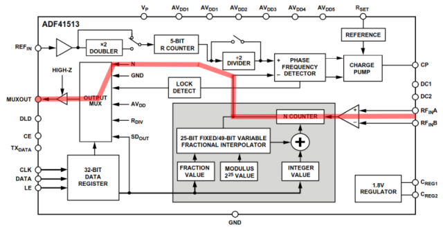
ADF41513 PLL IC used only for internal N counter in order to extend the range of frequency counter. Frequency divided signal is available on MUXOUT pin. Maximum input frequency is up to 26GHz, maximum input level +5dBm. According datasheet, RF input sensitivity is better for 8/9 prescaler option.
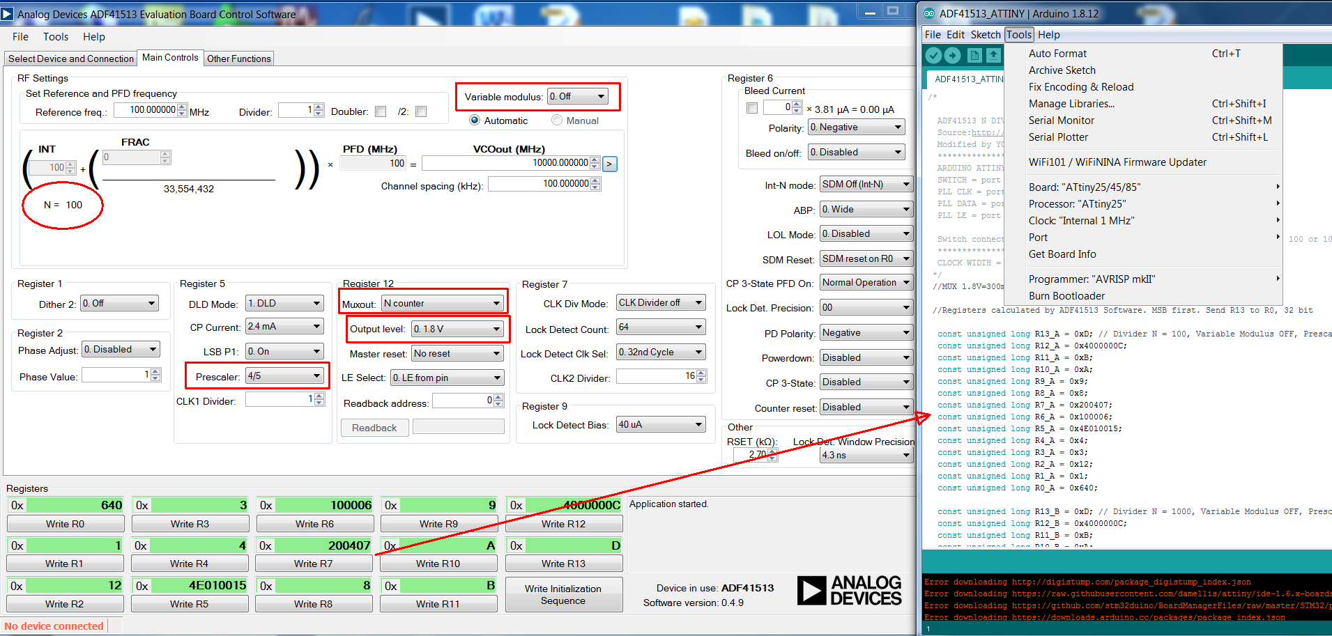
Dividing ratio can be modified according necessity by changing registers inside of Arduino sketch. All 14 registers are calculated using ADF41513 evaluation software, free download from Analog Device website.
Integer N mode supports any value between 20 and 1023 (range limited by 4/5 or 8/9 internal prescaler).
For my purpose two useful ratios 100 / 1000 were programmed. Power restart of uC is required if the ratio was changed by switch, because SPI words are sent only one time after power up.
Note: With small modification the project can be extended to normal PLL operation of ADF41513. Hardware platform must to be populated according ADF41513 evaluation board. Fore more details read EV-ADF41513 User Guide UG-1427.
The registers values will be calculated with same ADF41513 evaluation software and then inserted in the Arduino sketch to compile. During experiments Attiny uC can be replaced by any Arduino board (Uno, Nano, etc). In this way, after every registers modification, the software is fast uploaded via USB.
ADF41513 / Arduino digital pins:
LE = 0;
DATA = 1;
CLK = 2;
SWITCH = 4;
Registers configuration:
Divider N = 100; Variable Modulus OFF; Prescaler 4/5; MUXOUT N Counter; Output level 1.8V
Divider N = 1000; Variable Modulus OFF; Prescaler 8/9; MUXOUT N Counter; Output level 1.8V
Output option 1.8V is enough to trigger any frequency counter without to damage the input. MUX outpul level will be 300mVpp/50 ohms.
Also 3.3V can be enabled if the frequency counter is too lazy, MUX output 1100mVpp/50 ohms.
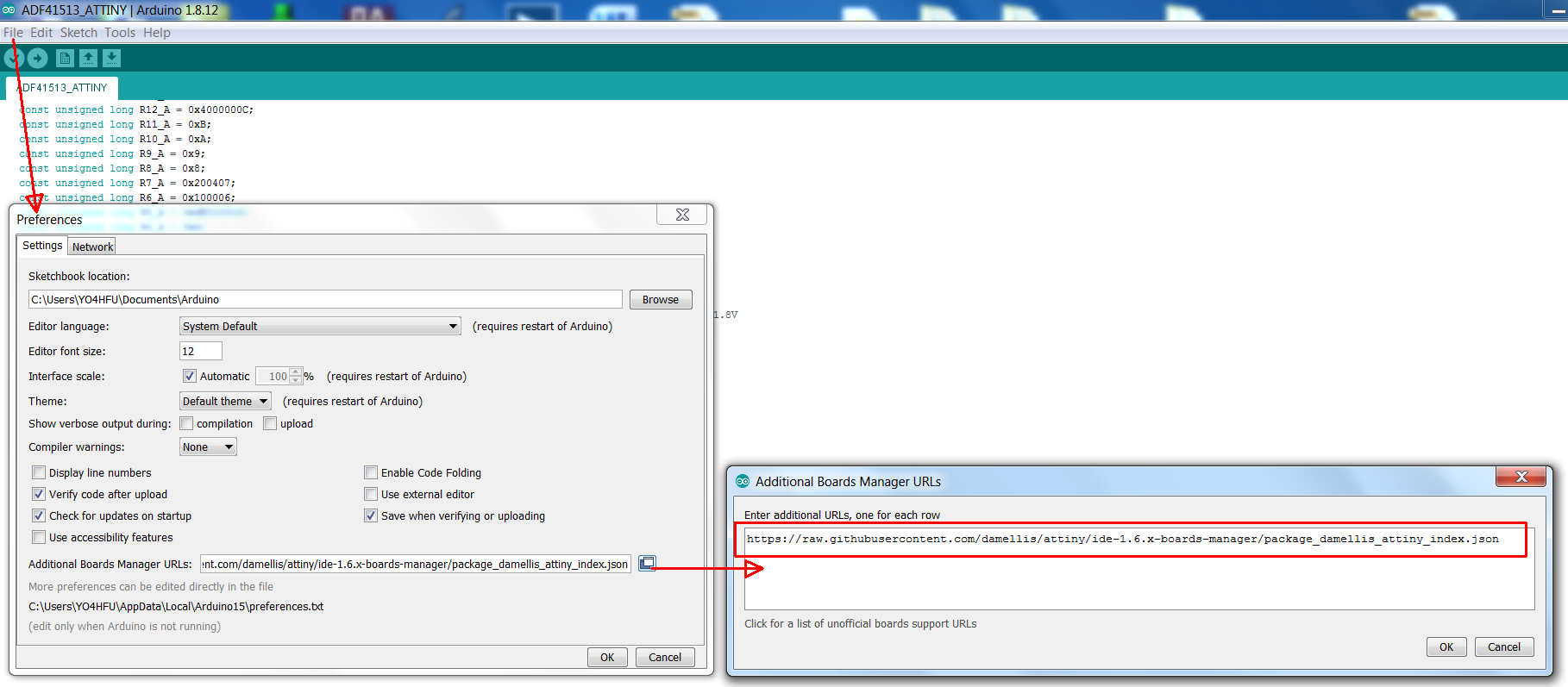
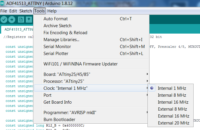
How to install Arduino Attiny board - ONLY IF YOU NEED TO MODIFY ATTINY HEX FILE:
If you want to modify the ADF41513 sketch and to generate new hex file, then Attiny25/45/85 additional board is required to be installed.
Open Arduino IDE. Go to File/Preferences. Click to add new URL on Additional Board Manager field: https://raw.githubusercontent.com/damellis/attiny/ide-1.6.x-boards-manager/package_damellis_attiny_index.json
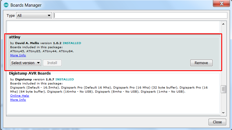
Press OK. Then go to Tools/Board/Board Manager/ search for attiny David A. Mellis and press Install.
Now you are able to find Attiny board inside of Tools/Board. Select Attiny 25/45/85 and 1MHz internal clock. Open ADF41513 sketch file and go to Sketch/Exported compiled Binary. Hex file location: Sketch/Show sketch folder.
Hex file (*ADF41513_ATTINY.ino.tiny8.hex) is ready to be burn by any Attiny programmer. If Attiny IC is new, default fuse bits are already configurated for 1MHz internal RC oscillator. Before Attiny programming is better to read and store the default values of fuse bits & calibration.
Update 2023: Attiny25 microcontroller supplied from same 3,3V regulator in order to increase input voltage range 5.5 ...12V.
![]()
![]() Schematic ADF41513/Attiny prescaler
Schematic ADF41513/Attiny prescaler
![]() Sprint Layout PCB
Sprint Layout PCB
![]() Arduino ADF41513 sketch
Arduino ADF41513 sketch
![]() Attiny 25/45/85 firmware (.hex file) for 100/1000 divide ratio
Attiny 25/45/85 firmware (.hex file) for 100/1000 divide ratio
![]() Evaluation software registers to Arduino IDE
Evaluation software registers to Arduino IDE
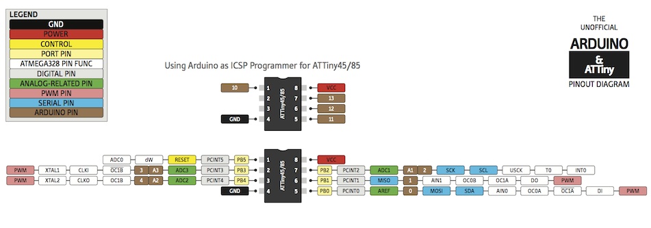
![]() Arduino pinout for Attiny 25/45/85
Arduino pinout for Attiny 25/45/85