
|
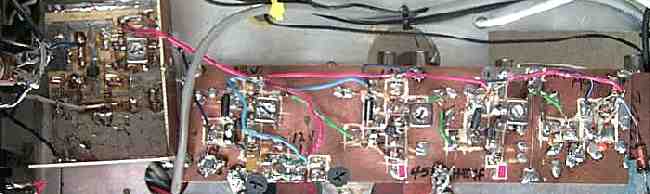
The complete IF strip. On the far left is the variable gain amplifier. A lot of gain in not needed here, so a Super Bright Blue LED is used and shines through the hole of the original headphone plug. The original Audio Gain pot is used to adjust the gain. In the middle of the image are the two AGC controlled MOSFET IF amplifiers. The first one has the circuitry for the S-Meter immediately below. The two PC mount 10K pots adjust the S-Meter setting. The third amplifier is the AGC amplifier. The AGC circuitry is to the right of the AGC amplifier. B+ is feed through the RF Choke seen at the far right. |
|
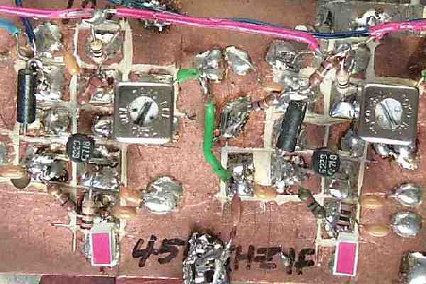
An image of the 2nd IF amplifier and the AGC amplifier. The output to the product detector is between the two amplifiers. The black long round objects are ferrite beads placed on Gate 2 of the MOSFETS. After this strip was built, it was determined that the ferrite beads were not needed. The LEDs are rectangular types at the bottom of the image. |
|
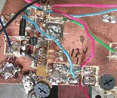
The transistor used here is a very obsolete 3N128. The AGC line is connected to the Gate, which is hanging in the air. It is difficult to see the connection to the gate lead. The two brown wires at the bottom of the image go to the S-Meter. The two PC mount pots adjust the S-Meter. |
|
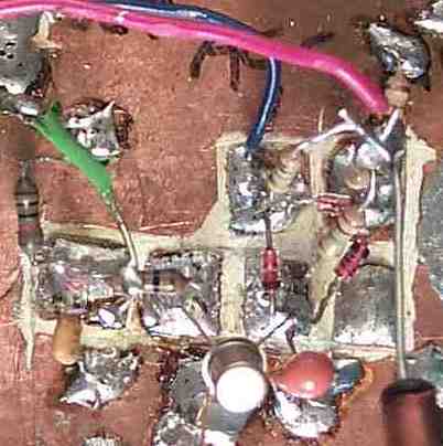
The transistor is a 2N2222, and a 10mfd tantalum capacitor is directly to its right. |
Send E-Mail || Amateur Radio Receivers || Super Receiver || Super Receiver Circuit Details