

|
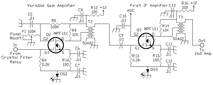
A variable gain MOSFET amplifier is placed at the front of the IF strip to provide an IF gain control. The 100K potentiometer and LED is mounted on the front panel of the receiver. The brightness of the LED indicates the gain of the amplifier. The variable gain amplifier is used to set the noise level output of the audio. If band noise is very loud, which it can be on 20 meters, the gain can be reduced to minimize the abrasiveness of the band noise. For quiet band conditions it can be run wide open. The LED is used to show the operator its setting. I used a Super-Bright Blue LED here. The Blue LED reduces the gain of the amplifier because of its greater foward voltage drop (3.5 volts versus 1.5 for a regular LED). The full gain of this amplifier is not needed, so the Blue LED works fine. This was mainly done for looks, a regular red could be used. The 455kHz IF transformer can be any that are available. The connection to the center tap of the primary gave more gain. It is worth experimenting with the IF cans to see which connection works best, either at the center tap or at the end of the coil. All the 455kHz IF cans I have seen have a center tap on the primary side. The optoisolator has been removed and the S-Meter moved to the AGC circuit. The benefit of having a visible LED helps with diagnosis of the circuit. A Murata SFU455A filter can be used at the input of the strip, connected between the mixer and the input to the IF strip. The filter has a 6db loss. This helps remove some noise and cleans up the signal from the mixer, but in listening tests with/without the filter, no difference could be heard. |
|
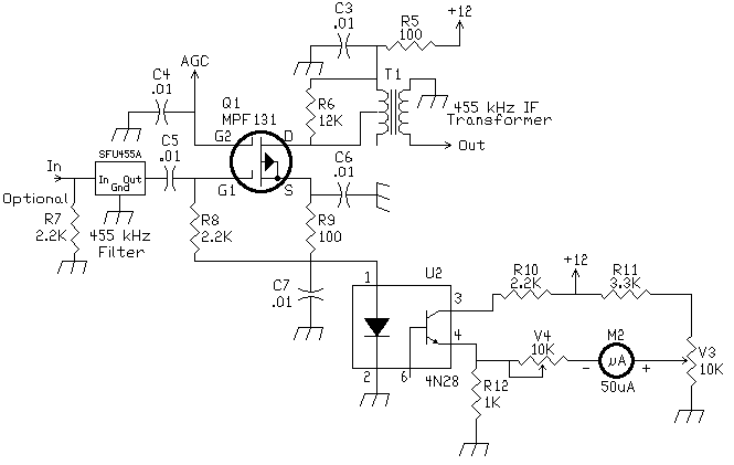
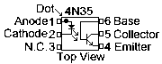
This was the first design of the circuit for the IF strip. It used a 4N35 optoisolator in place of the LED to drive the S-Meter circuit. This S-Meter circuit can be used instead of the updated one if desired. The First IF Amplifier can have a inexpensive 455 kHz ceramic filter at the input to filter unwanted noise from the mixer.] The 2.2K resistor at the input of the 455 kHz filter made no difference in performance in the tests that were run with it in the circuit, and tests with it removed. The input/output impedance of the SFU455A is approximately 2K. ReferencesThe Cadillac of all mosfet IF strips is "A Universal MOSFET IF Amplifier", by Georges Ricaud, and Doug DeMaw, QST, August 1981, Page 27. This circuit uses large red LED's which on the author's batch gave a 2.1 volt reference for the sources. He has two different AGC outputs, one that is used at the RF amplifier and one for the IF strip. He used a 100 ohm resistor in series from the drain to the transformer instead of a 2.2k resistor across the primary of the transformer as in the Progressive Communication Receiver. Ricaud also used a 100 ohm resistor at G1 as well as at the drain. Ricaud's circuit is great for using the MOSFET at higher frequencies, i. e., like the 9 MHz frrequency Ricaud's circuit is designed. He uses a MC1350 AGC amplifier, which is needed for good AGC action at 9 MHz.
 |
Send E-Mail || Amateur Radio Receivers || Super Receiver || Super Receiver Circuit Details