|
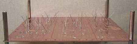
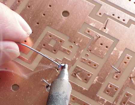
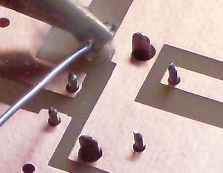
The picture above shows what the builder will be seeing most of the time when soldering the ELR - lots of wires sticking up at a 45 degree angle waiting to be soldered.
The parts in the picture are all the .01 capacitors inserted into Board 1, with a few soldered at the front.
Inserting the Parts into the Board
When parts with flexible leads are inserted through the board, bend the leads at a 45 degree angle to keep them in place when the board is turned over. Bent angle is not really important, but certainly enough so the part stays in place upside down.
Clip the leads after soldering. Point the leads away from your face when clipping the leads (save your eyes!). Most of the leads will shoot off like a rocket when clipping. Aim them into a trash can to keep them from landing all over your workbench and workroom.
Another technique is to hold the long leads with your finger when cutting. For shorter pieces, place your finger on top of the leads when cutting; they will fall on top of the board after being cut. A light touch is all that is needed, be careful not to poke or cut your finger.
Some leads will not bend: blue relays, 455kHz filter, 455kHz IF cans, MOSFETs, IRFU220, trimmer caps (2/8 and yellow) and the transformers (T4-6T and T1-1T). The 455kHz IF cans, MOSFETs, IRFU220, trimmer caps, and transformers will hold in place after inserted into the PCB.
The parts that will not hold onto the board (i.e., blue relays and 455kHz filter), add some solder to the soldering tip, then tack solder one pin to hold the part on the board. After soldering the other pins, go back and properly solder the tacked joint.
Common sense and creativity can also be used to get these parts properly soldered on the board. Any technique that holds the parts in place will be fine.
Soldering the Parts on the Board
The soldering on the kit boards mainly involves soldering small wires going through holes that are from about the same size to twice as large as the wire.
The solder needs to be on the wire, across the hole, to the ground plane or pad. The ground plane was designed to be as large as possible which makes it a very good heat sink. The pads were also oversized to make soldering easier and stronger for fixing mistakes and future experimenting.
The heatsink property of the boards is a slight problem, for the ground plane and pads sink a lot of the heat from the soldering operation and can prevent enough heat from reaching the leads of the components to get a good connect on the leads, especially large diameter leads or pins, for example, the 455kHz IF cans.
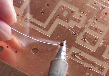
For quick, efficient soldering, apply solder to the component leads first, applying a small blob on the leads with the tip of the soldering gun with some additional solder added when touching the lead with the soldering tip.
Applying solder to the lead about 1/4" above the pad.
Then slide the tip and blob of solder down to the hole on the PCB, adding additional solder to get a good connection to the ground plane/pad. This ensures that the wire is soldered with a very good solder joint to the ground plane/pad.
Blob of solder shown on the pin before moving it down to the pad with the soldering gun tip.
Finishing the solder job by applying solder to the tip and ground plane covering the hole.
When learning this technique, put the solder tip about 1/4" above the pad and then move down to the hole. After some experience, you can move closer to the pad, always making sure the wire has solder on it before soldering to the pad.
Good job!
To find missing solder joints, hold the board in front of a light bulb and search the board for light coming through holes. Make sure the empty holes are NOT ones that were supposed to be soldered. Finish soldering missed solder joints.

Difficult Parts
Blue Relays
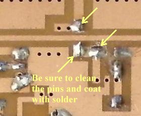
The 2/8 ceramic trimmer, the blue relays and the 455kHz filter are the most difficult to solder on the board. The reason is that the pins do not accept solder very well. The instructions specify to tin the pins before soldering on the PCB. Please don't skip this step.
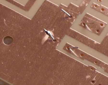
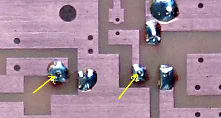
Arrows point to the bad solder joints on this relay. Notice that solder does not climb up the pin from the pad or ground plane and the distinct concave pattern around the pin.
Use a magnifying glass, if necessary, to check the relays pins after soldering.
There is not much room above the board to apply solder to the pin first, and then go down to the board, but it is possible. That is why tinning the pins beforehand is important.
The following does not show the 2/8 ceramic trimmer, but the same techniques apply.
455kHz IF Cans
DO NOT tin these pins before inserting into the PCB. You may not be able to get them through the holes. The pins are a tight fit through the holes.
The problem with the IF cans are the pins are so large. These pins take a little longer to get up hot enough to accept solder and do not extend very far above the board.
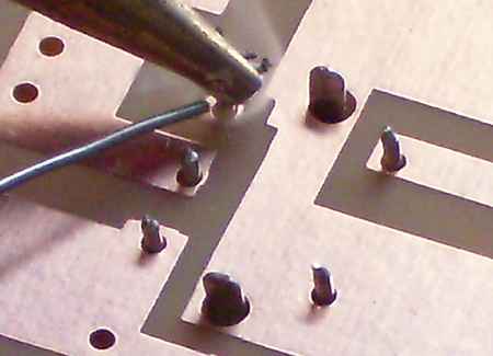
Place the soldering tip on top of the pin and apply solder between the tip and pin until it accepts solder, then go down to the pad and add a little more solder to finish the joint.
Tip on top of pin for heating to accept solder.
Tip moved down on board and adding a little more solder to finish joint.
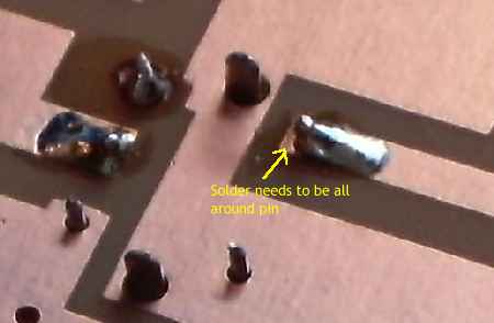
Be sure to get solder all around the pin.
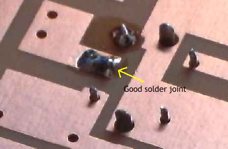
Good solder joint.
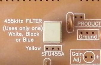
455kHz Filter
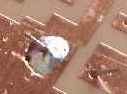
Picture shows correctly soldered pins.
If this part has a pin not soldered correctly, the S-Meter will show a noise level and indicate signals as you tune through a band, but no output at the speaker.
|