

|
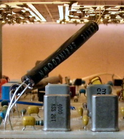
This picture shows the IR path between the Crystal Oscillator and the Crystal Filter when Board 2 is stacked on top of Board 1. The Phototransistor is mounted underneath the Crystal Oscillator on Board 2. Please notice the different location of the Phototransistor emitter tab when soldering in the Phototransistor. |
|
Black tubing isolating the IR path between the Crystal Oscillator and the Crystal Filter. If one of the LEDs is barely turned on, the Crystal Oscillator will oscillate at both frequencies, emitting a very loud howl out the speaker of the receiver. Since the Phototransistor is sensitive to ambient light, a bright room or sun reflecting off an interior wall will half-way turn on the Phototransistor (emitting a howl from the speaker), or completely turn it on, which will leave you wondering where the signals went on the band. The tubing used here is 3/16" vacuum hose, available from auto parts stores. The black heat shrink tubing supplied with the kit works just as well. |
|
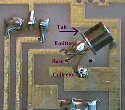
This picture shows the location of the tab and the connections of the Phototransistor to the bottom of the board. Align the traces on your board to the ones above and your placement will be correct. (Board Upside down.) |
Send E-Mail || Amateur Radio Receivers || Electroluminescent Receiver
