
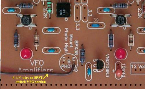
| The Phototransistor at the VFO Amplifiers is not installed. A 8 1/2" wire is connected to the "E" terminal of the Phototransistor footprint. The other end of the wire is connected to an SPST switch at the VFO. |
|
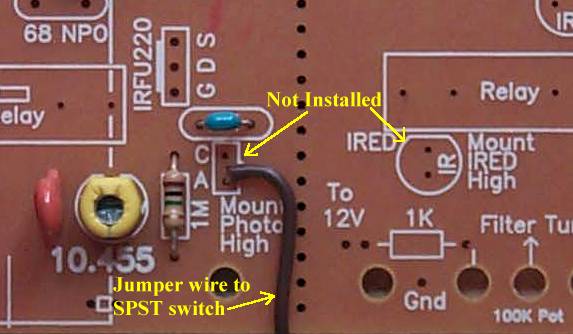
Shows the Photodiode on the VFO Section and IR LED on the Bandpass Section that are not installed. A wire is soldered to the "A" terminal of the Photodiode footprint that goes to a SPST switch to control VFO switching. |
Send E-Mail || Amateur Radio Receivers || Electroluminescent Receiver
