
|
Three cores are wound for the mixer/amplifier combination. One is wound with just a bifilar winding that goes in the center of the mixer/amplifier combination. Two are wound with a bifilar winding and a secondary of 5 turns which fit on each end of the mixer/amplifier combination. To save time, do each step on the three cores simultaneously in an "assembly type" operation, doing the bifilar winding on all three, and the 5 turn winding on only two of the bifilar coils. |

|
Cut two pieces of #24 wire 10" long, and then twist them gently together - approximately one twist pre inch. NOT CRITICAL. The wire size shown in the picture is #22 for clarity. Your wire will look smaller. Use the smaller size wire if two sizes of wire are included in the kit (only the very early production kits has two sizes of wire - #22 and #24). The smaller size will be #24 wire. The core is the equivalent of Amidon's FT50A-75. 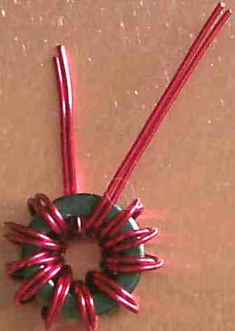 Do not pull on the wires with a lot of strength, the enamel can break off and short against the sharp edges of the core. Use only enough tension to get the wire wrapped around the core. Remember, you count one turn every time the wire goes through the center of the toroid. The first wrap you make around the coil will be turn number 2. You need ten turns for the first mixer/amplifier coils. The picture shows 11 turns, but you only need ten. 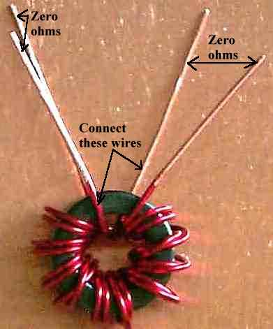 Use a VOM and place two wires that make continuity (zero ohms) opposite each other on the core, and make sure the two opposite wires on the other side make continuity. See picture above. In the picture above, the two wires on the left side measure zero ohms, and the two wires on the right side measure zero ohms. If you measure anywhere from 4K to 10K between any of the wires, the wires are shorted to the core. The enamel broke off and the wire is shorted to the core. Rewind the core with fresh wire or wind with insulated wire. #24 insulated wire (stranded or solid) will fit on the core. Use two different colors to make it easier to locate and connect the bifilar windings. Wire wrap wire will work very well and can sometimes be found at Radio Shack. 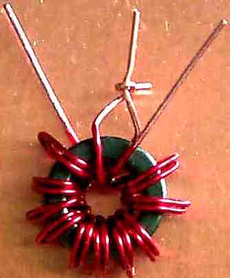 Take the bottom wire of one winding and wind it together with the top wire of the other winding. See picture above. Note: Version 2 of the PCB board, shipping from Jan 08, has enlarged center holes so the wires can be twisted together and fit into the PCB. The hole in the PCB (only necessary with the pink colored boards) will only accept the thickness of one wire, so you have to make a sharp bend on one wire, like in the picture above, leaving one pigtail to insert through the PCB. Check your work: Use a volt-ohm meter and check for continuity between all three wires. If done correctly, there will be continuity (zero ohms) between all three wires. Check between the two single wires then check between one of the single wires and the center wire (one with two wires). If you did it incorrectly, there will be no continuity (zero ohms) between the center wire (one with two wires) and the other two single wires. In other words, the two single wires will show continuity (zero ohms) but will not show continuity (zero ohms) with the center wire (one with two wires). If you made that mistake, just unwind the center wire and redo the connections. 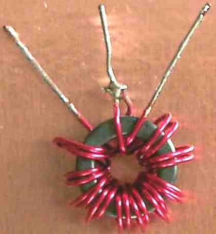 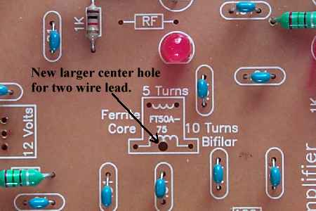
Note: The Version 2 of the PCB has a larger hole for the two connected wires so the problem stated here will be less of a problem. Double check this when soldering on the PCB before moving on to the next coil. There is no VOM check for this mistake. The receiver will work with the turns shorted, but the gain will be considerably less through the mixer (about 5dB). (Picture of shorted windings.) Tin the other wires with solder to help make a good solder connection on the PCB. One coil is made like this one and is placed between the mixer/amplifier combination. Two other coils are made like the one above, but a secondary winding is added as shown below. They are placed on each end of the mixer/amplifier. |

|
This picture shows the 5 turn winding added to the coil. This coil is used at each end of the mixer/amplifier combination.
Use a 6" length of wire and wind as nearly as possible in the middle of the core opposite the bifilar leads. 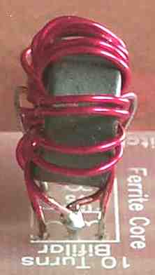
|
Send E-Mail || Amateur Radio Receivers || Electroluminescent Receiver
