
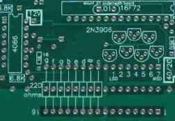
Soldering TipsThe best soldering tip is use is a very narrow one. Check this page for pictures of some tips. A temperature regulated iron is the best to use. Plated Through HolesThis PCB uses plated through holes. It is very difficult to remove parts from plated through holes unless you can remove one lead at a time. This means double checking all multiple pin parts (ICs, oscillator, voltage regulator, transistors) BEFORE soldering! If you solder a part and realize it is in wrong, you have to cut all the pins off the part to get it out, which means getting a new replacement. Email if you do this and I will help with a new part. Fitting/Soldering The ICsThe ICs have their pins flared out slightly. They will not fit into the board without a little adjustment. The pins need to be gently pushed in so they are straight down. This can be done with your fingers on each side of the IC pushing inward toward the middle of the IC. Go slow, check until they fit. Hold the IC against the board with one finger, get some solder on the solder tip, then tack on one lead of the IC to the board. Next, set the board down and solder another pin to the board feeding solder to the tip and pin and get a good solder joint. With your finger against the top of the part holding it against the board, reheat both soldered pins to get the IC firmly against the board. Finally, solder the rest of the pins. Large Soldering TipsWhen using a solder tip larger than what is recommended, the best way to make it work is to start by placing the solder tip ABOVE the hole on the lead, get solder to flow on the lead adding some solder to the soldering tip and lead. Then move the tip down to the hole, keeping the tip against the lead, add a little more solder. The solder should be seen going into hole. If you have a small round blob on top of the hole, try again, and check the top of the board to see if the solder has flowed through the hole. To Cut or Not to Cut the BoardThe board can be cut into two boards through the rows of holes in the middle of the PCB. See below.  Cutting the board now, before populating the board, is a lot easier. However, you can change your mind later. If tin snips are not available, a straight edge (i.e., a ruler) and a utility knife can be used to score both sides of the board through the holes. Go as deeply as you have patience for, then break apart. If you are planning to mount the frequency counter between Board 1 and the bottom unetched PCB the boards need to be cut. If you plan on building a case for the receiver and mounting the frequency counter on the front face, then you may not need to cut the boards depending on your design. Also, other projects may not require the boards to be cut. |
Fixing Ground Plane ErrorThere is a break in the ground plane on the right side of the board (viewed on bottom side). This break will be fixed on most of the boards sent out, but you must double check this first and fix it if not previously done. If fix is done, click here to skip to next step. This ground plane break will cause problems when the boards are cut across the holes. On the bottom of the picture above you will see "Ground Connection for 4077 pins". If this hole is cut so that the copper does not connect the top and bottom grounds, the 4077 will lack a ground connection. Fixing the ground plane break on the right side of the board will fix the ground for the 4077 IC. If the 4077 IC is not grounded the counter will be locked with a blank readout. 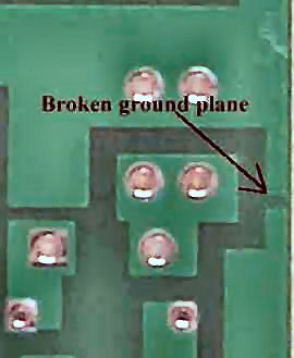 Closeup picture of the ground plane brake.
The fix is simple. Scrape the soldermask from the ground plane just above and below the break with a sharp knife, razor blade, or 220 grit sandpaper. Then solder a wire across the break. See pictures below: 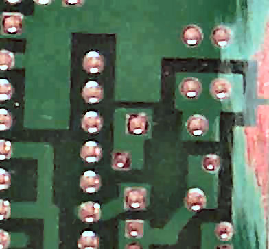 A closeup of the soldermask removed with 220 grit sandpaper.
Easier to do than the picture represents. 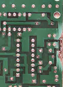 Tin the exposed ground plane first, then a wire
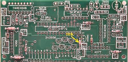
(or piece cut off from resistor or capacitor) is soldered across the gap. Step 1 - ResistorsThe footprints for the resistors have the value printed inside the footprint. Double check the value when inserting a resistor. Bend the leads of the 1/8 watt resistors about 1/16" from the body of the resistor to fit into the footprint. The leads of the 1/4 watt resistors are bent right against the body of the resistor. The 220 ohm resistors will not be inserted in this step. 1 - 10K, 1/8 watt, bend leads 1/16" from body
3 - 1K, 1/8 watt, bend leads 1/16" from body
4 - 100K, 1/8 watt, bend leads 1/16" from body Clean the leads on these resistors if they are dirty/black.
2 - 6.8K, 1/4 watt
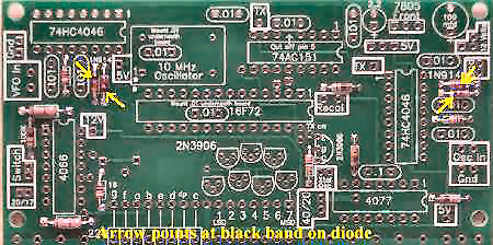
Step 2 - Diodes4 - 1N4148 diodes, bend leads 1/16" from body
Make sure the black band on the diode is inserted the correct way. The wide white band on the footprint is where the black band should go on the diode. To double check, the bands should be opposite each other at each pair. Step 3 - Capacitors1 - .1 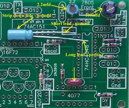 8 - .01  2 - .01 bottom side of board - Do not solder now!  These will be put on the board in Step 8 after the ICs and 10 MHz oscillator have been soldered on the board. Step 4 - 2N3906 TransistorsIf you get flared leads on all 8 of the transistors, see picture below, straighten the leads of seven transistors before inserting into the board.
___First - Cut transistor from cardboard. Transistors which have straight leads need a slight offset for the center lead as shown on the far right transistor in the picture above. It is not necessary to push the transistors against the PCB. The footprint for the transistors was necessary because of the tight fit between the traces for the LED readout and that meant a slight offset for the center lead was needed. 7 - 2N3906 straight leads Insert 3 2N3906 in the top row. Notice the flat side
of the transistor and match it to the footprint flat. Check for solder bridges and bent wires shorting against adjacent pins after soldering and clipping all the transistor leads. Solder bridges can be easily removed by wiping the tip of the soldering gun between the pins. 1 - 2N3906 flared leads
Cut the transistor from the cardboard and insert in the place indicated above by the yellow arrow. Note: This step was overlooked in the first run of the instructions, so that is why you do not see this 2N3906 on the board in the following pictures. Step 5 - 7805 and 10MHz Oscillator 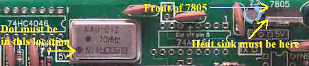 The 10 MHz oscillator can must have the dot in one corner at the lower left hand side as shown above in the picture. The dot is in the footprint and just outside so you can double check after the part is in place. The 7805 voltage regulator must have the front of the part toward the outside of the board. Also, the front side of the part should be pointed to the part number "7805". The metal heat sink for the 7805 is the back of the part and should be toward the center of the board. See picture above. Step 6 - PIC IC socket 28 pin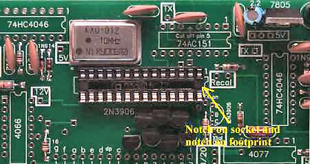 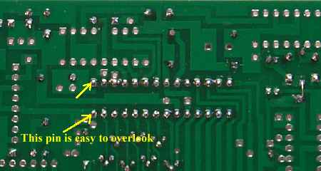 The one on the bottom can easily be overlooked as there are other holes very close by. Step 7 - Solder 5 ICs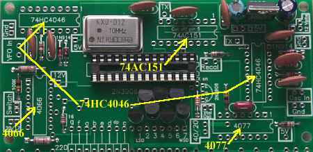 There are 2 ICs that require special attention. The first one is the 74AC151: 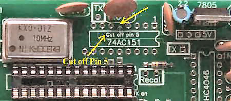 The second one is the 4077: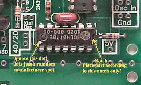 Next, insert and solder the 2 74HC4046 and the 4066: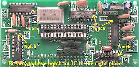 Step 8 - Solder two .01 caps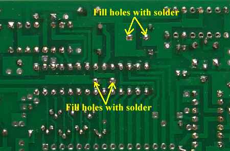 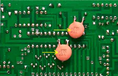 Step 9 - Solder the 7 LED displays 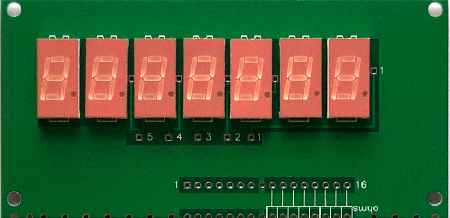 Step 10 - Solder the 220 ohm resistorsOne Board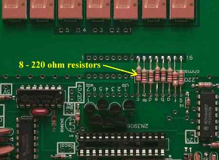 Cut Board - Two BoardsIf the board is cut at the row of holes, the 220 ohm resistors are used as spacers between the two boards and soldered. Then the cut leads are used to make connections between the other 8 connection holes (1 through 7 display drivers and ground). 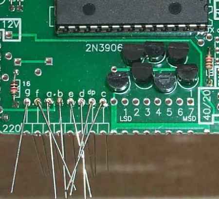  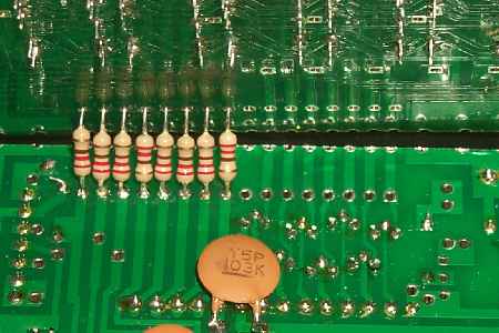 If you are going to mount them parallel, then no spacing is required, with the pic board bent down from the LED board (to provide maximum spacing from Board 1 of the receiver to minimize interference), then another 1/8" spacing is good. 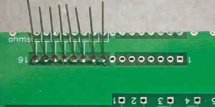 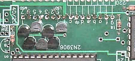 MSD means Most Significant Display, LSD means Least Significant Display. 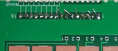 Step 11 - Insert the PIC16F72 into the SocketRemember to bend the pins toward the center of the IC until they are pointing straight down. Look down the rows of pins to make sure one is not bent further toward the center than the others. If one is bent too far, it may bend against itself or against the bottom of the IC, not going into the socket correctly. This will cause an intermittent error when the counter is turned on. 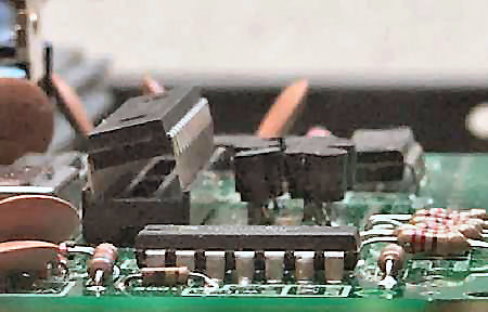 Lay one side of the pins into the socket, do not push down. 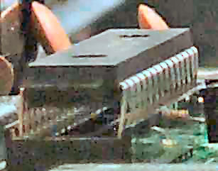 Roll the other side of pins into the socket. They may not fit in. If they don't, push on the pins slightly with your finger until they slip into the socket. Or, bend them some more toward the center of the IC and try again. Be careful, go slowly. 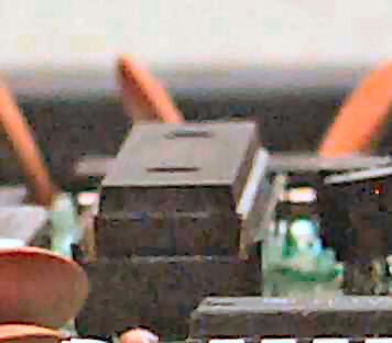 Now push down on the IC to set into the socket. Look down each row of pins to make sure, as best as can be seen, that all the pins are inserted into the socket. If you do bend a pin, either up onto itself, or up against the IC, carefully straighten the pin. Reinsert the IC watching the previously bent pin to make sure it goes into the socket correctly. Using needle nose pliers makes straightening a pin easy. You can get away with one rebending of a pin for sure, a second rebending of the same pin gets a little iffy, three, maybe not. |
 A couple of clippings are used to make connections for the "VFO In" and "GND". A couple more clippings are used to make connections for "12 Volts" and "Gnd" connections. The clippings are made into a tight U shape, inserted from the back side of the PIC board, twisted together, and soldered. Apply a signal from a signal generator or the receiver VFO to the VFO IN and GND connections. While watching the display, apply 12 Volts to the 12 Volt and GND connections.  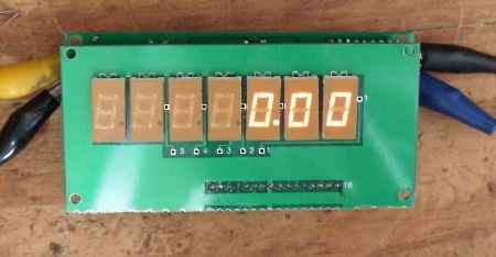 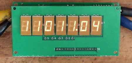 If your counter follows the sequence above, then it is in proper working order. The counter fixed this way can be used as a general purpose frequency counter for any purpose. Disconnect the short across the OSC IN and Gnd connection before continuing to "Connecting to the Receiver". |
Send E-Mail || Amateur Radio Receivers || Electroluminescent Receiver || Back to Ham Radio Instructions
Back to LED Frequency Circuit Details