
|
The description that follows is a result of my building some clear plastic cases for the Electroluminescent Receiver Kit. I have found the most important aspect of building a case is accurate cuts and holes. Before starting any cutting or drilling, practice with some scrap pieces so you don't loose any valuable pieces of plastic or trim. The first decision is how you want to mount the main tuning capacitor. For best stability it is soldered on the bottom of Board 1. It can be left off the board and mounted to the front of the case, but then a long connecting wire has to be run from the capacitor to Board 1, which causes vibration problems. In all my builds, I have chosen to solder the main tuning cap to Board 1. If Board 1 is dated 2000 (lower right hand corner), the mounting of the capacitor puts the shaft too far back to put a large knob on the shaft after the front plastic piece is installed. If you have a 2000 Board 1, see Electroluminescent Receiver - Main Tuning Cap for the Year 2000 Board 1 for instructions on moving the main tuning capacitor. Boards 1 dated 2005 and 2015 have the capacitor moved forward on the PCB and remounting is not necessary. Both Board 1 and Board 2 are mounted against the front plastic piece of the case. Flush mounting provides extra stability for the boards and the front panel. Accurate holes have to be made, but there is enough slack that minor errors can be made without problems. Building the plastic cases starts with cutting the bottom wooden piece and trim, cutting the plastic, front panel holes and making labels. The back panel has a couple of options. There are special drills for plastic that will be shown. |
|
The bottom board is made of wood of any type. I have used 3/4" plywood, various hardwoods, and just junk that used to be shelves. One-half inch pieces are too thin to make grooves deep enough to hold the plastic sides. Trim from the local hardware store fits 3/4" pieces of wood a lot better than 1/2" wide pieces. The saw is an imported table saw which will not make a straight cut unless a straight edge is used to make sure everything is lined up properly. The following pictures show the room and the saw. 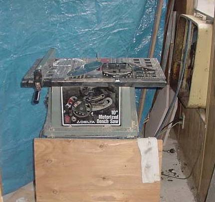 A table saw creates huge amounts of sawdust when cutting. First, put a large piece of plywood in front of the saw to keep the dust from getting on clothes and shoes. Second, a 9' by 12' blue tarp was hung from the ceiling behind the saw to catch all the sawdust from the back side. Third, a large box fan is put in the window to suck the dust out of the room. Some dust got in the rest of the room and tracked into the rest of the house, but it was tolerable. Without these precautions the room would be full of sawdust. |
|
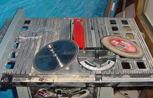
The table saw sells for $100 new at the local hardware store but I would not recommend it for anyone doing serious sawing. Nothing lines up and only the very carefull use of a straight edge yielded any straight cuts. A lot of practice cutting with scrap wood helps make accurate cuts. Use safety glasses! It only takes one un-protected cut to get something in your eyes. I found that the cheapest plywood blades make perfect 1/8" wide cuts. The expensive blades cut too wide. The plywood blade also cuts the plastic. On the table is a metal cutting blade. After experimenting with this blade I did not use it. It made nice clean cuts in wood, but it would wear down quickly and the burning smell afterwards was not worth the trouble. |
|
This board is about 12" wide by 11" deep. This will allow a back plate with connectors. If you do not use a back plate, a 12" wide by 10" deep piece would work. The advantage of not using a back plate is that it is a lot easier to take apart to make modifications or repair. All the connectors can be soldered to the ground plane of the PCB boards. A back piece will make using coax connections a lot easier and provide a professional look. The best place to emphasize the LED lighting is a mirror along the back above a 3" aluminum piece at the bottom to hold all the connectors. Cutting the Grooves |

|
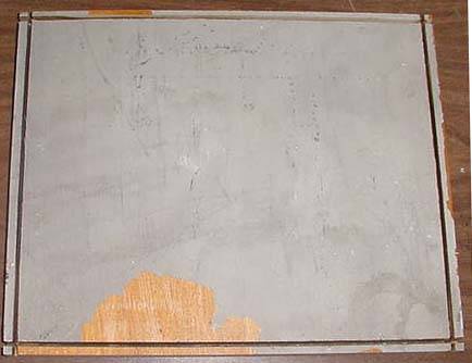
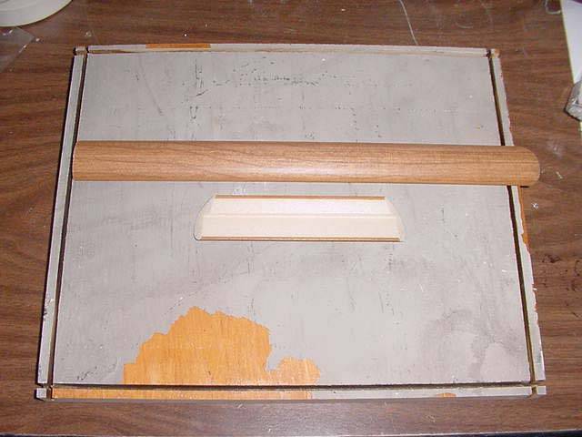
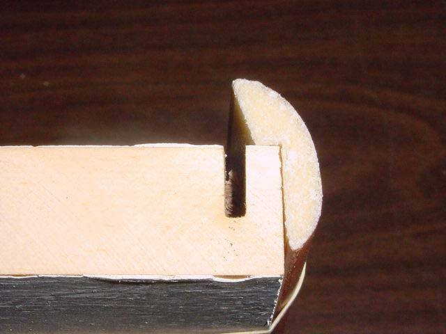
The pictures above show how the trim is placed on the side of the bottom board. The trim was available at the local hardware store and was inexpensive. The side plastic pieces are 1/8" thick plastic lexan or acrylic. I found mine in an automotive/house glass repair business. The top piece is 1/4" plastic. The bottom piece on the top picture shows the 45 degree angle cuts that are made at the ends of the trim pieces. The trim pieces are longer than the width of the bottom board to allow for the angled pieces to fit together without a gap. On my build, the pieces extended 3/16" beyond the edge of the board on each side. This means the trim piece is 3/8" longer than the width of the bottom board. The trim piece will be 6' to 8' long. Practice with a couple of pieces to get it right on the first cut. I didn't get it right the first or second time. With the trim piece held against the edge of the board, you can see how far back the cut for the plastic pieces have to be. The bottom picture above illustrates this distance. When you have determined the distance back from the edge of the board where the plastic has to be, then cut the groves. The groves are cut 7/16" to 1/2" deep. Check that the saw makes the right width cut with a spare piece of wood to see how the plastic pieces slip into the grooves. |
|
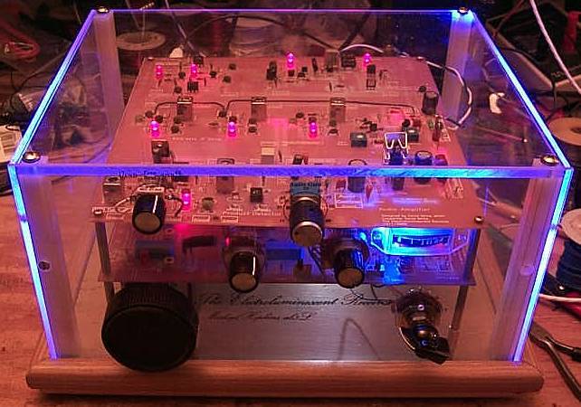
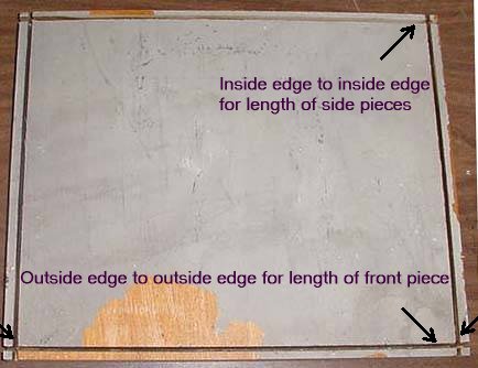
The side plastic pieces are 1/8" thick plastic lexan or acrylic. I found mine in an automotive/house glass repair business. The top piece is 1/4" plastic. I asked for discounted scrap pieces to see if they had some large enough. If you live in a large city, you might find a plastic manufacturing company that sells scrap plastic sheets. Cutting the plastic with a plywood blade left rough edges which reflect the light of the LED's. Suppliers cut the plastic with heated wires leaving a smooth surface that does not reflect light. To get the blue light on the edges of the plastic you need rough edges. If you have smooth edges, just use fine sandpaper (100 to 220 grit) to rough up the edges. The height of the plastic pieces are 6". The case at the top of the page does not have a back piece. Connectors were soldered to the ground plane of the PCB boards. The back was open. Three pieces are cut, two sides and one front piece. I let the front piece go all the way across the front and the sides pieces went behind the edges of the front piece. There will be differences in the bottom boards: measure as shown in the picture below. |
|
To hold the corners of the plastic sides and to hold the top piece, 1/2" square pieces of nylon plastic are cut and screwed in place from underneath the bottom board. I obtained my nylon plastic 1/2" square rods from a local printing company. Called "cutting sticks", used as stops for paper guillotine machines. The cutting blade hits against these square rods after cutting a stack of paper. After a couple months, they replace them with new ones. My friend at the printing company had several used ones he gave me. They are 30-1/2" long, but their are several sizes depending on the size of their cutting machine. You can find them at Printer Supply Companies: Graphic Equipment, ULINE, and Graphic Art Supplies. Some sell individual lengths for $18, so it would pay to check your local printing company for used ones. The length of the corner pieces are measured with the front or side plastic pieces in place. Measure from the bottom board to 1/4" from the top. The reason for the 1/4" short is that I used a 1/4" thick plastic top that fit inside the plastic sides. The square pieces are held in place with screws in the corners with the plastic sides in place. Mark the outside of the square on the board. Then mark the center and drill though the board. 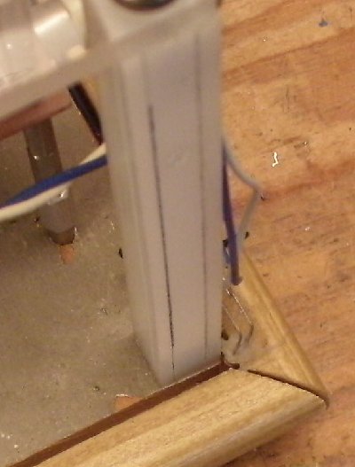 Size of the screw is a 6-32 about 3/4" long. Drill a 9/64" hole (for 6-32), and then from the bottom side, use a 1/4" drill to enlarge the hole so the screw can be inset into the hole to shorten the length of the screw needed. A 1/4" washer can be used to give a solid base to tighten the screw in the hole. To thread the bottom of the square rod, use a 7/64" drill bit and use a 6-32 tap. Some of these square rods from the print shop have holes in the middle. If you get one of these, there is a fine thread metric size that fits it perfect - no need to tap, they screw in nice and tight. The outside diameter of the screw is 3/16" (threads and all) - don't know the thread/metric size at this time. 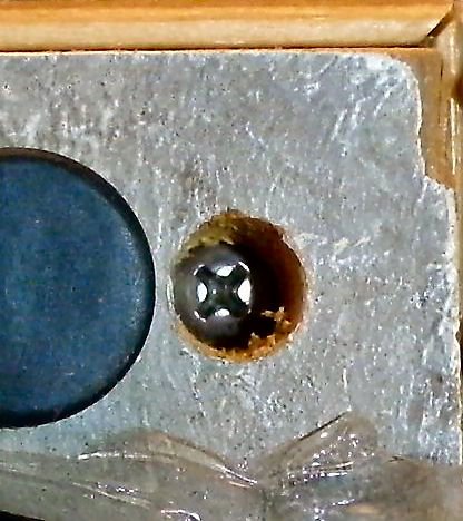 Holes are drilled through the plastic sides and into the square supports and taped for 4-40 screws. First drill with a 5/64" (or No. 43 drill bit) through both the plastic and the square support. Lift the plastic side out of the way, then tap the square support with a 4-40 tap. Then drill through the plastic sides with a 1/8" drill bit to allow the 4-40 screw to slip through to the treads on the plastic support. I used flat head screws with a countersink (cone shaped under the head) for a clean appearance. If you use these screws, countersink the holes to give room for the countersink on the screws. See the picture below.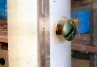 I found one screw was needed. At the front I used a screw one half the way up and on the sides I used one 2/3rds of the way up the side. 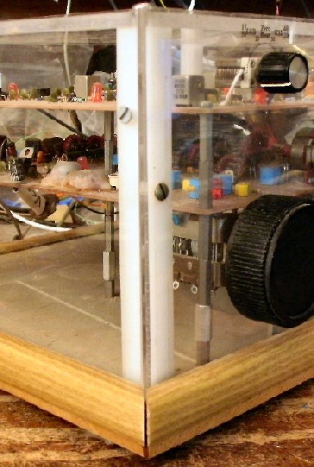 Below are the tools used to drill, tap, and countersink the screws. 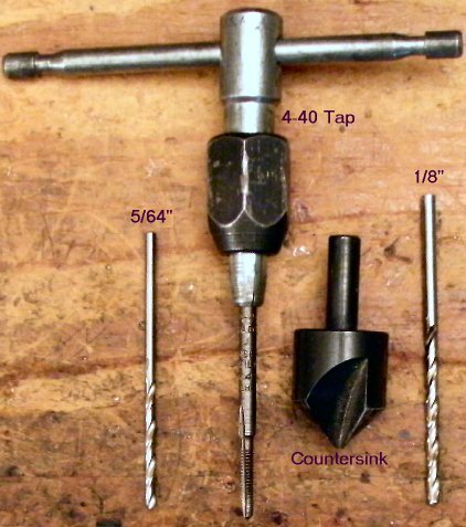 |
|
When using a front plastic panel, the switches for the Bandpass Filters and Crystal filters are no longer available. A rotary switch or four DPDT panel mount switches must be added and wired to the front panel. DPDT switches are the cheapest way. Doing a Google search for rotary switches can sometimes find inexpensive rotary switches. See
Using a Rotary Switch for LED Frequency Counter Band Changing for wiring a rotary switch.
To get the front panel holes and labels organized, I would recommend a free HTML program called WebDwarf V2, by Virtual Mechanics. WebDwarf has a very detailed grid background and by using the arrow keys, you can move the labels and text in very small increments to move it just exactly where you need. A WebDwarf file consists of three parts: a geometry folder, an image folder and an .ims file. You put these in the MYsite folder, in the Documents folder in My IMS Projects. The My IMS Projects folder in made in the My Documents folder when the program is installed. Double click on the .ims file and the layout should appear on screen in the WebDwarf program. The labels are .gif pictures which can be edited in a picture program: Paint Shop Pro, LView Pro, Gimp, or others. You can edit or make new ones as you desire and then load them into the WebDwarf program using the Add a Picture icon on the left side (Picture of Mona Lisa). When you are finished, click on Publish, make note of where it is going (Local Publish Directory), and hit Publish. A index.htm file will be in the My IMS Projects folder. Double click on this file and it will open in your default browser. Print the page in Landscape format with regular paper, cut or punch out the holes and test for fit on the receiver. Note how far you are off on any of the controls, go back to WebDwarf, make adjustments, re-publish, print and check again. Use the correct layout on print paper to drill your holes in the front plastic piece of the case. Use masking tape to hole the paper layout in place while marking the holes. Before printing the final layout on a clear plastic sheet, the logo at the bottom left of the layout in the browser needs to be taken off. Load it in a Mozilla browser, click on Tools (Menu bar), Web Developer, and then Inspector. At the bottom you will see a list of the elements on the page starting with div id=Oobj5, go down to the last Oobj number and you will see footWH. Putting your mouse over the text of the logo will highlight the footWH also. Left click to highlight and the text of the logo will be highlighted above in the layout. Then right click and click on Delete Node. After deleting footM2 will be highlighted (which was below the footWH). The logo should be highlighted. Then right click and click on Delete Node. Save the page in the browser Menu (File, Save As) and put it in the same directory as the index.htm file. (My Documents, My IMS Files) in case you need it again. Print with a piece of clear plastic sheet (laser printer and laser plastic sheet preferred), punch or cut out the holes, put on the back side of the front plastic piece of the case and install with the controls and down into the slot and against the side square posts. You can get the laser printable clear plastic sheets at an office supply business. The one I went to let me buy individual sheets instead of a whole package, which can be expensive. Drilling HolesWhen drilling the small holes (up to 1/4") in plastic, a regular bit for steel or aluminum will work. For larger holes, a steel bit will crack the plastic. For the larger holes, use a bit for wood cutting. It has a center tip and two cutting guides on the outside edges of the bit. See the picture below. These bits are found in hardware or lumber stores. 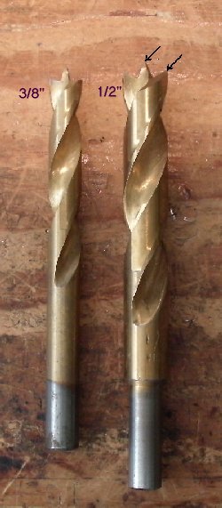 |
|
|
|
|
Send E-Mail || Amateur Radio Receivers || Electroluminescent Receiver
