Translate this page:
Modifying the AL82, AL1200, and AL1500 to run cooler in Digital Modes
Modifying the AL82, AL1200, and AL1500 to run cooler in Digital Modes
What I did notice was only medium heat over the tank area. Complete opposite of what I could
feel with the cover on it. It seems that a lot of the heat from the 3-500s is being pushed
up into this area, and preheating the tank area, then the heat developed in the tank area has no
place to go. I do not think there is enough exhaust area over the tubes,
especially the one towards the center of the amp on the early AL82's. This, plus there being no exhaust area over the
tank area, puts the components in that area under excessive heat conditions. Failed Band Switches
are common when used in digital modes because of the high duty cycle develops so much more heat.
Caution: High Voltage
Read this, and use caution while doing anything inside of amps
with the cover off. This is about guitar tube amps, which are
constructed simalar, but use much
lower voltages.
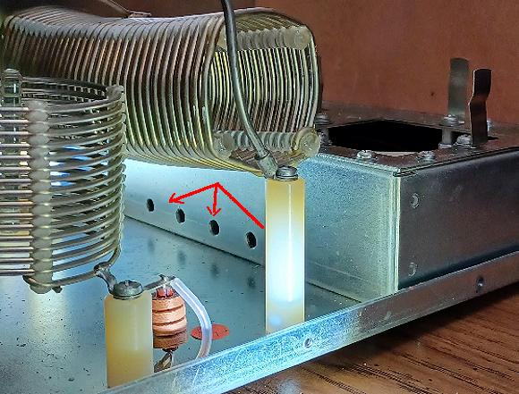
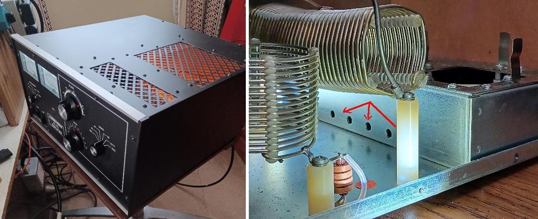
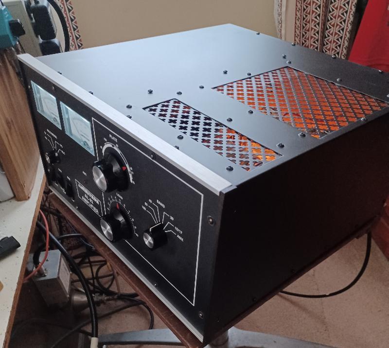
This shows where the 5 holes were added to provided
some more cooling air to the band switch and tank area.
For High Power RTTY use, the tank area, left of the tubes needs more cooling and heat extraction. The biggest problem, is over heated and damaged band switches. The insulating material supporting the coils also gets hot, sags, and deforms, causing other problems.
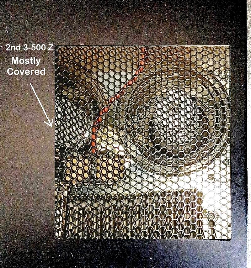
I ran it hard remote for a few hours on several bands with the cover slide back, and could not detect any
excessive heat over the tank area. I would really like to open up the exhaust area more over the
inner 3-500 , like the AL1500 has, and over the tank area. I would of course use some expanded metal similar to what
the factory used for safety and RF. Doing the cover exhaust mod, the higher output fan, and the
holes under the tube chassis shown below, should solve the heating problem in digital modes. These Amps have no cooling
problems in normal use, or light digital use, it is only during heavy high power 100% duty cycle use like
in RTTY Contest, or even long SSB Contest.
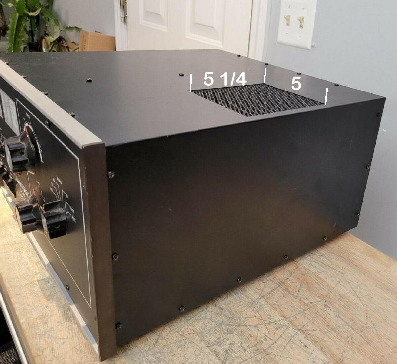
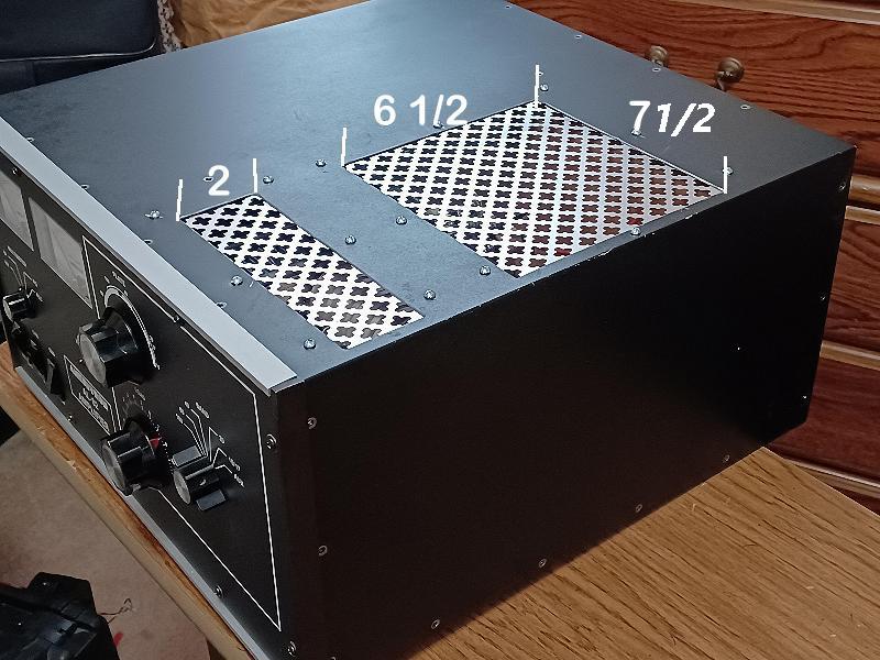
The original cover had 26.25 square inches of exhaust.
My modified one has 48.5 square inches over the tubes,
plus 15 additional square inches over the Band Switch.
The cover was Powder Coated to maintain the factory look.
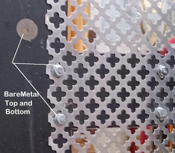
Since we are dealing with very high RF Levels, make sure that any changes in this area, that you maintain Ground between each part of the cover and the chassis. You should have bare metal to metal contact, and any screws should make contact with bare metal.
I do a lot of RTTY, and other Digital Communications, which generate a lot of heat.
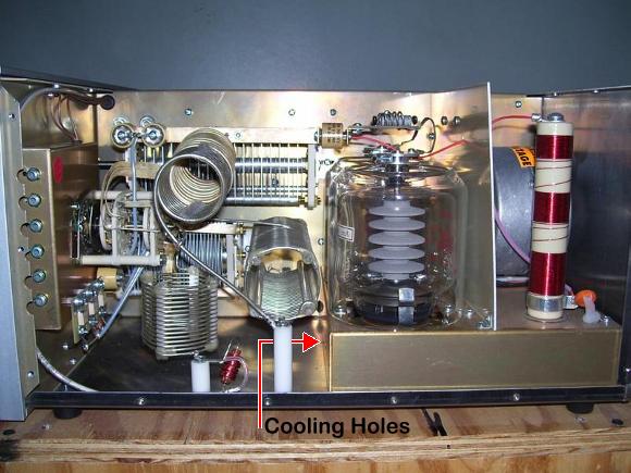
I will also install the high output fan. I added a row of holes across the front edge of the tube chassis.
With a higher output fan, it will send some cool air up front to the tank area, while also increasing
the air flow to the tubes.


This will take some cool air directly from the fan, and direct it towards the tank area, keeping components at a reasonable temperature. I already have a 2 position switch installed on the back to use full speed on the fan for digital modes, so that will be nice with the higher output fan.
With the high output blower below, and a row of small holes made in the tube chassis, a exhaust area over the tank area,
cooling will no longer be a problem under the heavy load that digital modes put on equipment.
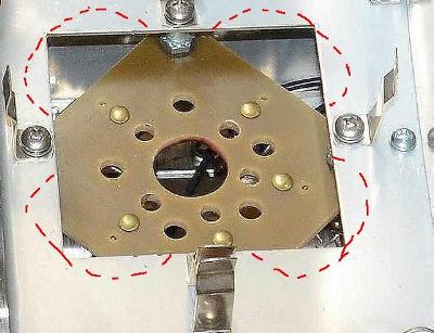
Some guys have had the contacts of there band switch burnt, but on mine,
one of the inner wafers of the band switch called a rotor had gotten too hot,
and some of the metal arms had lost there temper. They did not make good
contact with some of the band contacts, and no contact at all on others.
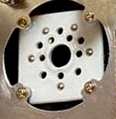
This is what the rotor wafer looks like. During heavy RTTY use, the heat
caused the little metal arms to loose the temper.


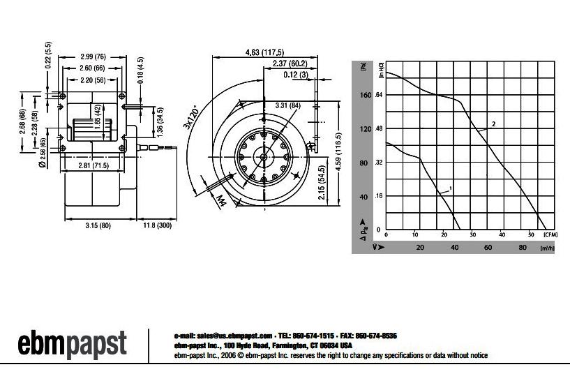

Tom Rauch (W8JI) at CTR Engineering, the guy that designed these amplifiers, has these
high flow blowers with the required run capacitor available at a Great Price. He also
has Band Switches.
The AL82 uses fiberglass tube sockets, which are fine, but during extreme use, do
restrict air flow. You can improve cooling to the tubes by switching to a less restrictive
tube socket, or opening up the metal area around the tube socket , but inside the chimney
area. This will cool the tubes better, and reduce back pressure, thus lowering noise.
When Ameritron changed to the fiberglass tube sockets, they were supposed to change the shape of the metal opening around the sockets to allow more air flow, since the newer sockets restricted the air flow. They were also supposed to provide some air flow to the front area, around the band switch and tank area, by making some small holes on the forward edge of the tube chassis. Doing these two things, will provide better cooling to the tubes, provide some cool air to the front area, and reduce back pressure on the blower, which will reduce blower sound level.


Put the tube chimney clips back on, and be ready for better cooling, with less noise.
Make sure that any drilling or cutting that is done on the tube chassis, is done with it removed, and care taken not to hit anything on the bottom of it. When finished, vacuum and use canned air to remove any small particles.
If you are uncomfortable modifying the tube socket area, you can increase the tube cooling some, by lowering the socket by using longer mounting screws, and just adding a small nut to lower the socket. This will allow more air to flow around the tubes.
Below is a SK-410 High Flow Socket that cost about $40 each. This type would of taken care of the
tubes just fine. Taylor makes a identical one, that is about $30 each.

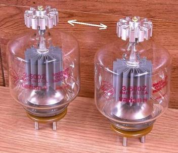
These Anode Plate Caps are designed to lower the temperature of the top of the 3-500
seal area. These seals are not a known problem, but these will also help to pull
some heat off the tubes, which should help extend there life. Wider ones are better
than taller ones, since they put more of the fins into the air stream. Avoid too
tall, to keep the Plate HV away from the cover. They also add a little "Bling" :)


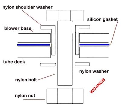
To reduce blower noise to a minimum, add a rubber type isolator under the blower, and use
nylon bolts and nuts to mount it. This will help reduce vibration and noise.
Ameritron started using a silicone gasket under the newer amp blower motors, and the
part number is 770-3737.
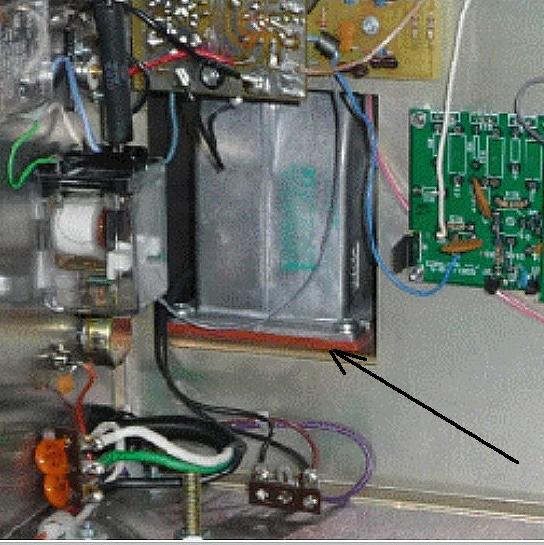
Below is a good mounting method, that will reduce noise and vibration sent from the blower motor, through the amp housing. No metal to metal contact.
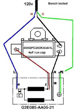
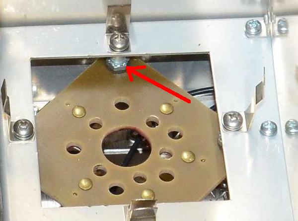
Adding a 2 speed blower switch to your amp.
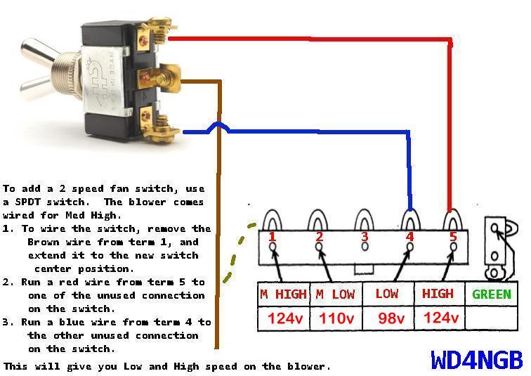
Terminal 1 and 5 have the same voltage on mine
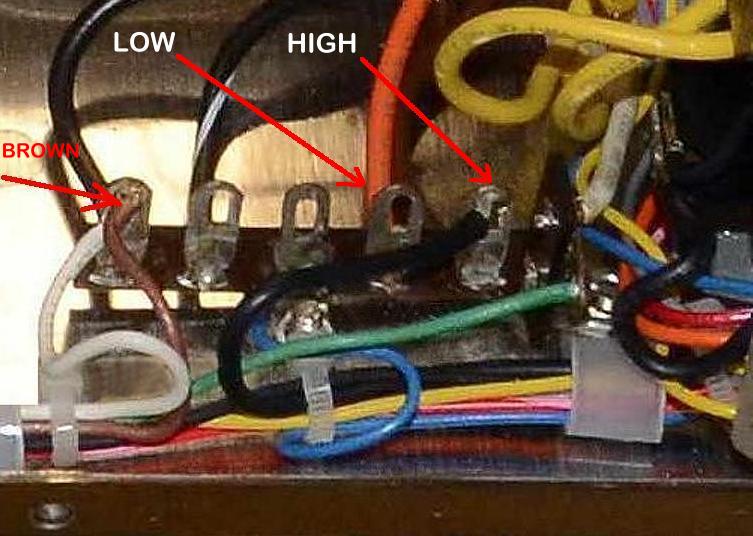
The red arrow show term 1, and the Browm wire
Adding sound deadening material inside will lower the sound even more if still needed.
Self sticking sound deadening material like Hush Mat works great, just
make sure what you select will handle some heat.
These photos courtesy of K6JRF

You can reduce the sound level even more be adding sound diverters to both the inlet, and exhaust area similar to this. They need to be placed so the the sound from the blower is diverted away from the operating position. Make sure you do not direct the exhaust towards the other side, as it will be pulled back into the inlet.