TRB-1 Triple Ratio Balun
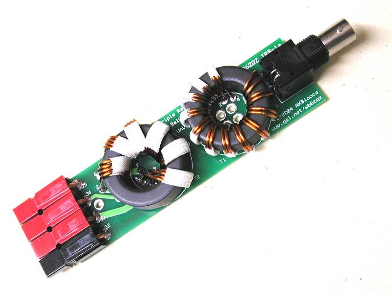
The Triple Ratio Balun PC Board Production Version
Note this photo is of the First Article which does not have the production
color coded Powerpoles
Document Ver 1.23 01/20/2005
Introduction
Users of High Frequency (HF) Portable Antennas, Beam Antennas, Mobile Antennas,
Dipole Antennas and Vertical Antennas
- this Triple Ratio Balun
solves some of the problems that you may have experienced!
If you have been unable to achieve low SWR (Standing Wave Ratio)
when trimming or adjusting your antenna
you may be suffering from impedance mismatch, unwanted common mode feedline current,
or both.
This Triple Ratio Balun is very effective at solving those problems!
Impedance Matching
In many antenna systems the impedance just is not exactly 50 ohms.
This can be due to proximity of other objects, height above ground,
or just the antenna's design.
The Triple Ratio Balun provides the flexibility necessary to match
a range of impedances which encompasses most resonant antennas up to
a half wavelength in size.
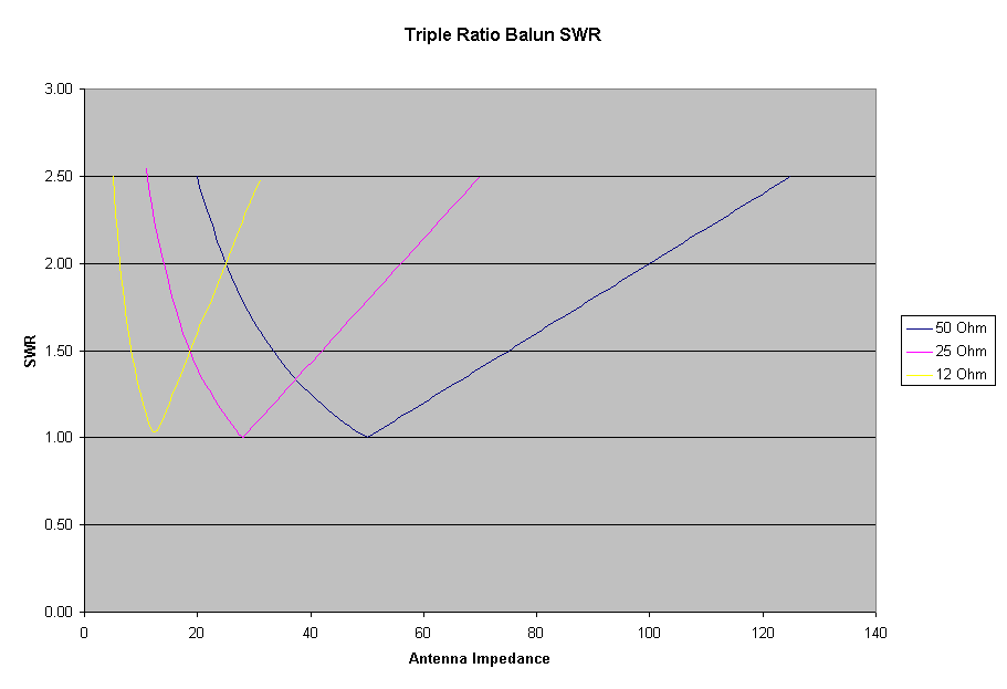
Three taps are provided that provide 12 ohm (1:4), 25 ohm (1:2) and 50 ohm (1:1)
impedance ratios.
This provides a match resulting in a Standing Wave Ratio under 1.5:1
for resonant antennas with impedances from 8 to 75 ohms.
In the 6 to 8 (or 75 to 100) ohm regions the SWR will still be a (usually)
acceptable 2.0:1 or better.
The TRB (TM) is not an antenna tuner - if there is reactance at the antenna
ports it will be transformed to a reactance at the BNC terminals.
A tuner at the radio end of the feedline can then be employed to resonate
the system.
RF Isolation
For those enjoying HF portable operation
(such as Field Day or Emergency Communication work),
or the new HF Ultraportable operations such as HFPack
(see www.hfpack.com)
there are often problems with RF getting into the wrong places -
locking up the mic, causing distortion, etc.
(This can be especially problematic on digital modes such as RTTY or PSK31).
(This can also be a problem in HF mobile installations).
Touching the rig (or the antenna analyzer) may cause the SWR reading
to change substantially.
This indicates that the system is imbalanced and there is RF flowing on
the outside of the coax (undesirable) and getting onto the outside of the
radio cabinet, microphone, etc.
The Triple Ratio Balun includes a Line Isolator as a part of its design.
This provides a high reactance to current flow on the outside of the coax and can
dramatically reduce if not completely eliminate this undesired current.
This will keep the current flowing on the antenna and counterpoise and off
the outside of the radio!!
Note that an antenna without any kind of counterpoise DEPENDS on the
current on the outside of the coax and radio cabinet as these form the effective
counterpoise.
In this case a line isolator is not desired and may reduce the performance
of the system.
However it is generally more effective to use an actual physical counterpoise of
some type
and then the isolator will keep current on the counterpose and off the radio
and help prevent the problems stemming from current flowing where it does not belong.
Mobile Antennas
Mobile antennas generally have very low impedances on the lower HF frequencies
due to the extreme loading and small radiation resistance of a short antenna.
The Triple Ratio Balun will often solve this problem
and produce a better match to the feedline at the antenna.
It provides three impedance transformation ratio settings which is sufficient
to provide the desired low SWR over a wide antenna impedance range.
The isolation is also helpful in preventing RF current flow on the outside
of the feedline that often occurs due to the inherent ground loop of a mobile setup
(the radio is grounded both through the power cable and through the coaxial feedline).
Vertical Antennas
The feedpoint impedance of quarterwave type vertical antennas is in the neighborhood of
35 ohms and the
Triple Ratio Balun is well suited to both match these impedances and
inhibit undesirable common mode current flow on the outside of the feedline
which is often a problem with verticals, especially those with a low to moderate
quantity of radials.
Portable Antennas
Shortened antennas may have even lower impedance depending on system losses.
This includes base, mobile and portable vertical, horizontal and L antennas,
especially those that are inductively loaded.
The TRB is ideal for antennas of this type, both providing impedance transformation
and common mode choking reactance.
Beam Antennas
Beam antennas often have impedances much lower than 50 ohms due to the coupling effects
of the other elements.
For beams that have feedpoint impedances greater than 6 to 8
ohms this Triple Ratio Balun can be a viable substitute with much wider bandwidth
than the sometimes troublesome
feed systems commonly employed.
For homemade beams the Triple Ratio Balun can be
a simpler option than Gamma, Delta, or other matching systems, providing both
impedance transformation as well as significant choking impedance against unwanted
feedline currents that can seriously degrade the front to side and front to back
performance ratios that beam antennas are designed to provide.
Quads and Loop Antennas
Quads and other loop antennas often have impedances at or below 50 ohms and
the TRriple Ratio Balun can be used to match to the feedline.
The same feedline radiation concerns exist as with the beam antennas -
current imbalance can cause degradation of front to side or front to back
ratios - and the isolation characteristics of the TRB are beneficial there.
Dipole and Inverted Vee Antennas
The TRB also works well with fullsize dipoles and inverted vee antennas.
If the antenna is near the ground or other objects the impedance may be
much lower than free space.
The TRB provides flexibility to select a lower impedance for a good SWR,
and it provides choking reactance against imbalance and feedline radiation.
Hot Baluns
Have you ever noticed a balun that gets hot? In some situations some designs do.
Try putting a full power CW carrier through your favorite balun and see if it gets
warm at all.
Testing should be done at several frequencies.
Heating is most likely to occur at the lowest or highest frequencies or
at the frequency of highest antenna impedance.
There are many
types of balun designs, but in some situations they may have insufficient choking
reactance, or may employ magnetic materials that have inadequate bulk resistivity
for the application frequency.
Depending on the materials and design they may generate
considerable heat.
One thing to keep in mind here is where that heat is coming
from.
It is energy from your transmitter that should be in the antenna,
but has been lost.
Some baluns depend on flux linkages to transport power, and this
is less efficient than the transmission line technology used in the Triple
Ratio Balun. This can also lead to heating of the core.
If a balun gets hot enough (an extreme case) the magnetic materials can become
nonlinear, and in this case the balun can actually generate harmonic energy!
The Triple Ratio Balun uses materials and design that have been optimized
for very low loss and high choking reactance in the HF frequency range.
This reactance is very predominantly inductive (due to the choice of magnetic material),
so the lossy resistive component
of this choking reactance is very small.
This is a highly effective balun design with very low loss ferrite cores
and high temperature high voltage heavy gauge insulated wire.
Bead Baluns
Bead baluns are wonderfully simple and effective on various cables for reducing
RFI.
Bead baluns on transmitting feedlines can be problematic.
If there is no imbalance they are fine.
If there is a sufficiently unbalanced condition even a small
current flow on the exterior of the coax can generate considerable heat in the beads
and waste energy.
If the beads become sufficiently heated they can become nonlinear (again, an extreme
case) and actually
generate strong harmonic interference as mentioned above.
Beads are made from magnetic materials designed
for extremely high permeability to provide strong attenuation of RFI in cables.
At high frequencies these materials have both inductive
and lossy resistive properties. Since power is current squared times resistance,
even a very small imbalance current in a large resistance can dissipate considerable power.
Bead baluns are best when deployed in RFI suppression for video, audio and power cables,
receiving antennas, or for transmitting antennas that are balanced
(and don't actually need a balun).
If I interpret the manufacturer's charts correctly, at 3.5 mhz
the isolation winding in the Triple Ratio Balun is equivalent to 180
of the type 43 beads, or 85 of the type 77 beads usually used on RG58 or RG8x type coax.
The common baluns and kits use 2 to 5 of these beads.
It takes a great many more beads to perform as effectively as the bifilar isolator
incorporated into the Triple Ratio Balun.
The Triple Ratio Balun
This (photo above) is the Production (first article) version of the Triple Ratio Balun.
(Note that the kits contain color coded Anderson Powerpole connectors).
The impedance ratios are 1:1, 2:1 and 4:1 providing impedances
of 50:50, 50:25 and 50:12 ohms.
This balun provides impedance matching for antennas from 8 to 75 ohms
at 1.5:1 or better SWR (and 6 to 100 ohms at 2.0:1 or better)
by selecting from the three taps, as well as providing isolation for either
balanced or unbalanced antennas to eliminate or significantly reduce any current flow
on the outside of the feedline. It uses extremely efficient transmission
line transformers. The development pages (link below) contain detailed info
about the development of this design.
The power handling capability of this balun exceeds 100 watts.
It was tested by applying 100 watts CW for a few minutes and then checking
for heat. Heat rise in the wires on the cores was barely detectable.
No heat rise was noted elsewhere. The BNC connector may be the limiting
factor on the power level. Leaving the connector off and soldering coax
directly to the PC Board is an option for the builder.
After further testing the power rating of the TRB will likely be increased,
but I want to be extremely conservative at this time.
The frequency range of this balun is at least 3 to 30 mhz.
Reports of useful operation on 6 meters have been heard as well, but
I have not done testing there.
A high quality double sided plated through hole solder reflowed printed circuit board
with solder mask and silkscreen makes the balun straightforward to build.
The unit as shown above weighs about 3.5 ounces.
Using the Triple Ratio Balun
This balun is best placed near the antenna feedpoint.
The BNC (50 ohm) is connected to the radio via the feedline.
The Anderson Powerpoles are used to feed the antenna with impedance selection options.
I use my TRB with a variety of antennas including the Buddipole
(from W3FF Antennas at http://www.buddipole.com/).
and Buddistick vertical configuration.
The Triple Ratio Balun is also
effective with screwdriver, Hamstick, Hustler, Iron Horse or
other hf mobile or portable antennas.
It should perform well at the feedpoint of most HF beam antennas whose
impedance falls within the range of the TRB.
The Buddipole high quality compact loaded dipole is resonated by adjusting the
coil taps and whip lengths.
The impedance of the Buddipole varies with frequency and physical
configuration.
For example, on 40 meters the Buddipole's impedance is low enough
that the best SWR usually occurs on the 12 ohm balun position.
I have spoken with several people who are planning to try the TRB with
the Pac-12 antenna (http://www.pacificantenna.com/).
This should work quite well.
The Triple Ratio Balun has been used with the High Sierra Sidekick mobile
screwdriver antenna (http://www.cq73.com) to reduce the SWR when a top hat was used.
The adjustment procedure is easiest using an antenna analyzer.
Set the antenna up, starting with the manufacturer's settings
and check the resonant frequency (lowest SWR reading).
If this frequency is lower or higher than desired first make adjustments in the
coil taps and whip lengths to move the resonance to the desired frequency.
Then select among the three balun settings (12, 25, 50) to choose the lowest
SWR reading.
In some cases a very slight tuning adjustment may improve the SWR further if
the tap is changed from the original position.
Below is the computed SWR graph for the various taps and resonant antenna impedances.
It should generally be possible to get 1.5:1 or better SWR.
Record the settings and start there next time.
In general the lower frequencies tend to use the 12 or 25 ohm settings,
while higher frequencies use the 25 or 50 ohm settings.
Adding arms or longer whips often increases the impedance (and the efficiency)
of the antenna requiring a higher impedance setting of the balun.
Adding more ground radials may REDUCE the impedance, but again the efficiency has
improved due to lower losses. Improving coil Q also may reduce the impedance and
increase efficiency!
Availability
The Triple Ratio Balun kits are available.
The kit includes a high quality PC Board, cores, wires, tape and connectors -
about 20 pieces in all.
It includes one set of Anderson Powerpoles for the antenna connections.
(Additional Anderson Powerpoles are available from many vendors).
The contents of the kit are listed in the instructions on the web
via the link below.
Order the Triple Ratio Balun Kit below.
Or go for the two-fer deal kit that contains parts for two baluns
at a reduced price.
.
Ordering
Visit our Product Order Page
Links
WB6ZQZ Home Page
 since July 2004
Please send any Feedback to the author at the address below.
You may email author Alan Biocca via wb6zqz at arrl.net
Triple Ratio Balun and TRB are trademarks of AKBiocca Engineering