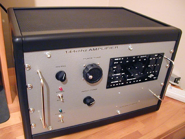
"My Version of a 3cx1500/a7
8877 144mhz W6PO amp"
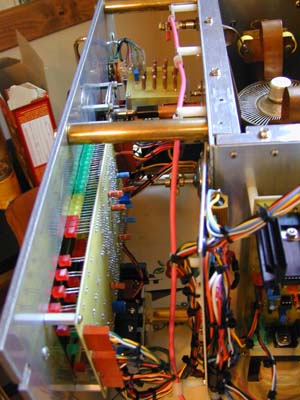
(I am
running a little over 4kv on the plate. Amp will do over 2kw
out)
Give the page time
to load. There are several Pic's on this page to load.
To see what it looked like before + to see the
HV supply click
here.
Look
here
for where to get the parts for this. Thanks Paul WD7S
Look here for where to get the
Jennings RJ1A or Kilovac HC-1 relays. Thanks Allen
WB4GNT.
(either the Jennings or Kilovac will work fine)
Some things the new W6PO has that a stock W6PO does not
have.
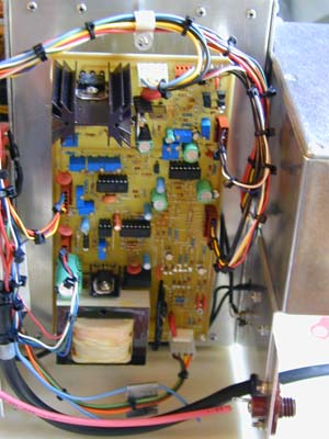
Triode
Control Board
1. ADJUSTABLE WARM-UP TIMER; HOLDS OFF HV AND
KEY LINES
2. ADJUSTABLE GRID OVER-CURRENT
FAULT, AUTO-RESET
3. ADJUSTABLE GRID
OVER-CURRENT WARNING LED
4. ADJUSTABLE PLATE
OVER-CURRENT FAULT, SHUTS DOWN HV SUPPLY IN 8.3 MS OR LESS
5. TUNE/ARC FAULT, UN-KEYS AMPLIFIER WHEN SEVERELY
MIS-TUNED OR DURING TANK CIRCUIT
ARC, AUTO-RESET
6. HV PRESENCE FAULT, HOLDS OFF KEY LINE IF HV NOT
PRESENT OR LOW AFTER WARM-UP
7. FULL BREAK-IN QSK USING
VACUUM RELAYS, LESS THAN 2.1 MS
8. T/R
FAULT, HOT SWITCHING PROTECTION
9. FULLY ADJUSTABLE
OPERATING BIAS USING THE TL-431 ADJUSTABLE PRECISION REFERENCE
10.ELECTRONIC BIAS SWITCHING, 2.5 AMP MAX
11.DUAL KEY-LINE BUFFERS, EITHER +5 -16 VDC OR GROUND WILL
KEY THE AMPLIFIER,
(TTL AND CMOS COMPATIBLE)
12. COOL - DOWN DELAY FOR BLOWER, (OFF BOARD)
13. FRONT PANEL STATUS OF ALL FAULT AND OPERATING
CONDITIONS.
14. ZERO
CENTER TUNE METER, DETECTS INPUT AND OUTPUT POWER LEVELS AND
DISPLAYS
VARIATION FROM OPTIMUM GAIN
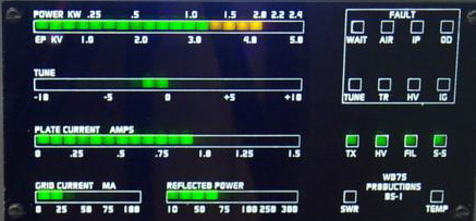
FIGURE
Bargraph Digital Display
1. ZERO
CENTER TUNE BARGRAPH, 20 SEGMENT
2. 14 FAULT AND STATUS LEDS
3.
HIGH
REFLECTED POWER FAULT INTERFACED WITH TRIODE CONTROL BOARD,
AUTO-RESET
4. 2.4 KW POWER BARGRAPH, ONE HALF OF MULTIMETER, 20
SEGMENT
5. 0 - 5 KV PLATE VOLTAGE BARGRAPH, ONE HALF OF
MULTIMETER, 20 SEGMENT
6. 300 WATT REFLECTED POWER BARGRAPH, 10
SEGMENT
7. 0 - 1.5 AMP PLATE CURRENT BARGRAPH, 20
SEGMENT
8. 0 - 100MA GRID CURRENT BARGRAPH, 8 SEGMENT
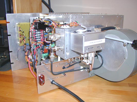
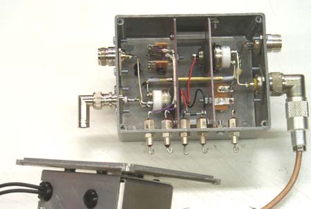
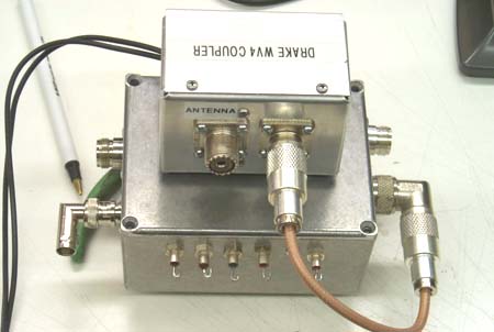
IF YOU USE VACUUM RELAYS
AND COUPLER NOTE THE BELOW
FOR 144mhz
*Note - the vacuum relays can not be installed in main RF
deck due to
radiation
from the open contact connections on the RJ1-A's. They need to be
shielded
in a seperate RF
encloseure.
*Note - most RF couplers like Bird 43 type will not work. They do not put
out
enough voltage to drive the display ckt. You could try adding an op amp
to
try
to get the Bird coupler voltage up to about >2.5 vdc.
*Note - You may need to add a small trimmer cap
around 10pf to ground in
bypass
mode
to tune out possible inductive reactance to get VSWR down to <
1.5:1
*Note
- It is very important to keep all connection lead lengths as short as
possible
*Note - If you want the relays to operate/release really fast
apply +33vdc to
them
and
use a .33mf @500vdc capacitor across the relay coil instead of a
normal
reversed
bias diode setup.