|
|
|
For an extremely clear and detailed AC-1 schematic, click HERE to visit the BAMA site. |
|
|
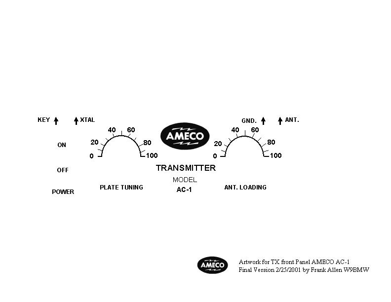
The Powerpoint (PPT) file can be customized to your requirements. The Jpeg (JPEG) file can be printed out and given to a silkscreener to create a negative/positive to make a screen. Courtesy of Monte W9BMW/7 |
|
|
|
|
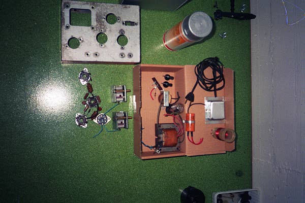
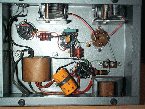
C1 20uf 450V electrolytic C2 400pf variable *Suggest http://www.danssmallpartsandkits.net/ C3 900pf variable *Suggest dual section 450pf ganged to make 900pf (CAV)920-0138 http://www.surplussales.com/
C4, C5, C6 .001uf 500V +80% -20% disc C7 220uf molded mica C8 .001uf 500V +80% -20% disc C9 22pf +-5% NPO disc R1 100K +-20% 2 watt R2 15K +-20% 1 watt R3 47K +-20% 1/2 watt
|
L2 RF choke 2.5 mh L3 RF choke 2.5 mh L4 RF choke 2.5 mh T1 - Power transformer Secondary voltages without load: • 6.01 V filaments AC • 320 V AC * Suggest Hammond P-T273AZ from www.tubesandmore.com
V2 6X5GT (or 5852) V1 6V6GT V1 DC mA plate current: • 22 mA (with old 6V6GT) • 40 mA (with NOS 6V6GT) RF Power output: • with old 6V6GT: 2.5 W • with NOS 6V6GT: 5.0 W
|
|
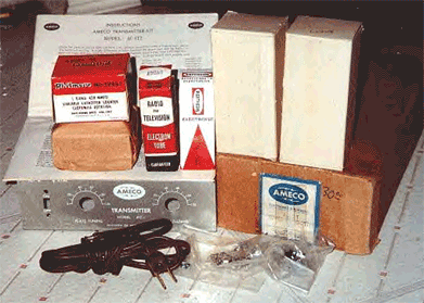
J1 Socket, octal, 8 pin, black S1 SPST Slide switch, black TB1 Terminal strip, two screw TS1 Terminal strip, 3 lug, 3AHA |
XV1 Socket, octal, 8-pin, black XV2 Socket, octal, 8-pin, black XL1 Socket, 5 prong (for plug-in coil form) |
|
L1 For 40 Meters: 15 1/2 turns of #22 enameled wire close wound on 5 prong coil form. For 80 Meters: 28 1/2 turns. (The AMECO coil form measures approx. the inside diameter of an octal tube socket and has a 5-pin base) * Suggest P-C211 from www.tubesandmore.com |
|
• A common question relates to the older and newer versions of the power supply. One has a choke input filter and the other a simple capacitor input. I have played with the power supply and find that the choke input filter really doesn't seem to give you any better CW note and actually the voltage is down and it decreases the output power. • The most significant thing that effects keying is R3 the 47 to 68 K resistor (depending on version and schematic) on the grid pin #5 to ground of the 6V6. It allows too much crystal current and is a real source of poor keying and a harsh chirpy note. The best values that I have found are 4.7K at a minimum and up to about 15K ohms. I use all types of FT-243 40 and 80 meter crystals with mine. They sound very nice with the lower R3 value. If the crystal current is too low at 4.7K and doesn't want to oscillate, just keep increasing it until it does. This should occur between 4.7 and 15K ohms. The transmitter will sound much better! • I have also increased my power supply B+ capacitor value to 20 and 30 mfd from the original 8 - 10 mfd they originally put in the kits. • Most people of course use a tuner today so the antenna loading air variable really does not have to be 900 pf. The transmitter will work well with two (2) 365 pf or 400 pf caps. If you intend to use the transmitter with a resonant dipole with no tuner of course the higher value 900 pf antenna capacitor is desireable. |
|
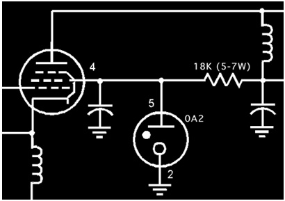
Banish "Chirp" Forever With... HOT ROD AC-1 TWEAKING TIPS FROM TREVOR, K6ESE (email) 1. Replace R3 with a 2.2K resistor (1/2 watt and higher). Replace C9 with a 10pf capacitor. OR... 1A. Replace R3 with a 10K (or most any value) potentiometer to vary the bias on the 6V6 to optimize various types and brands of tubes (6F6, 6L6, used or new 6V6's, etc). Replace C9 with a 20 or 30 pf trimmer capacitor to vary the feedback capacitance. 2. Beef up power supply B+ capacitor C1 value to 40 mfd. 3. Add an OA2 regulator tube (see schematic below) and mount it under the chassis (don't drill your original AC-1 chassis!) to stabilize the 6V6 screen voltage. R2 will have to be beefed up to an 18K, 5-watter. • The above mods works best with currently available Peterson Radio crystals - which are HC-6's - not FT-243's.
 |
