Our Portable Ham Shack - Part 3
![]()
|
The Solar Project For almost a year the three solar panels and charge controller stayed in their boxes. Now, as the warmer weather of May was at hand and Field Day fast approaching, the solar project could no longer be ignored. Without our solar panels, our portable adventures would be short lived.
We chose Uni-Solar US-64 solar panels. Though somewhat
more expensive per watt than Theoretically, the three panels could produce a total of about 192 watts (11.6 amps) at maximum power (which, of course, is seldom reached). They would handle our ham radio power requirements during the daylight hours and have the batteries topped off at sunset if we run reduced power for contests. It would have been nice to have more storage batteries, but the small size of the trailer makes that difficult. We are using two Group 27 deep cycle batteries now. Each panel is 53.8" high x 29.2" wide. It has an operating voltage of 16.5 volts and produces a maximum of 3.88 amps. The panels each weigh 20.2 pounds. With a 20-year power output warrantee, they will likely outlast me. Wiring The Solar Panels
Each panel includes a weather resistant junction box
with knock-outs, however I chose The solar charge controller was connected to the batteries, and all tested well. The panels were not ready to test at that time.
All connections from the solar
panels to the charge controller to the fuses to the battery will be
made with 45-amp The three panels are wired in parallel with 30" lengths of 10 gauge wire. The larger wire was used to ensure that very little voltage drop occurs between the panels and batteries.
If you don't want to bother with constructing your own
in-line fuse holders, Powerwerx makes a dual fuse holder with
Anderson Power Pole connectors Much to my chagrin, I later found much less expensive standard size ATC fuse holders listed on eBay, so search the auto parts stores and check on eBay before purchasing ATC fuse holders. Just be sure the wires are the gauge you want. Forty-five amp Power Poles will be attached to the 10-amp wires on the ones I bought. They will be placed into the circuit supplying current from the panels to the charge controller and fused at about 20 amps. The Solar Charge Controller
For our charge controller, we chose a "top of the
line" ProStar 30M (with meter) manufactured by Morningstar. At
first this seems to be over kill, but it has features we like and if
we decide to add more panels to the system later (perhaps on a larger
trailer?) it will handle the extra power requirements. Again, check The controller features "intelligent" charge controlling which promises to significantly improve our battery life and performance. Blocking diodes are not needed, as this unit has an internal one, however our panels also include them across each cell. The unit has a grey plastic housing and weighs 1 pound. Wires enter the unit from the bottom. The unit is mounted on the closet wall in the bathroom, as it provides a short route for wiring to the battery and an easier installation. In the installation directions, it states not to install the charge controller on a flammable surface, as the back of the unit may become very hot under some circumstances. While the unit has a heat sink on the back that does not touch the wall, I wanted a safer installation on the dry 21-year-old wooden paneling. My thought was to mount it on piece of ceramic tile. Not having a diamond-encrusted drill bit specially made for drilling ceramic tile, and not wanting to make an expensive purchase to make 4 holes in a 62-cent tile, I elected to try a new 3/16" masonry bit. This was going to be a time-consuming process, and I would have to use plenty of water to cool the bit and keep it from glazing over. Hmmmm... At this rate, it would take a long time to drill each hole, if it could be done. Time for plan "B": buy the diamond drill bit. A 3/16" diamond bit could not be found, so a 1/8" diamond core bit was purchased on eBay The bit worked great, but the holes weren't large enough. The 3/16" masonry bit had to be used to make them larger. This took some time, but not as much as if I had tried to drill each hole with it. The bit was also getting quite dull when the last hole was finally finished, so it probably wouldn't have drilled more than one or two holes without help from the diamond bit.
Since the paneling is so thin, I
placed a 12" x 16" piece of flake board A piece of 1/2" I.D. PVC pipe was inset in the trim board, and 10-gauge zip cord to the controller from the solar panels and the batteries runs through it. What comes in or out of the trailer must have a way to get through the walls. Therefore, a piece of 3/4" ID PVC pipe with an adapter for fitting a screw-on cap was used. Murphy visited the project once again this week when I went to install the pipe. After deciding on a location to drill a 1" hole through the thin aluminum siding, Murphy decided I should drill a few more inches to the left. I did.... right into half of the wall stud. I can still hear Murphy laughing about that little joke. Moving back to the right a few inches, I drilled a second hole and mounted the PVC pipe. A similar connection provides access for a cable from the solar charge controller to the battery box. A small chain was later added to each cap to prevent its loss.
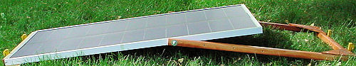
Testing The Solar Panels The three solar panels were hooked together for testing before mounts were built. We propped the panels up with folding chairs for this experiment and aimed the panels in the approximate direction of the sun and tilted them as shown, but nothing was done in a precise manner.
When power was connected to the charge controller,
everything worked on the first attempt. Over a period of about half Jane and I were very pleased with the test results. We still had a few issues to resolve, such as transporting the panels and building tiltable mounts. The panels also could use some bracing on the backs so they do not flex as much. However, in general, the project progressed on schedule. Roof Or Ground Mount? A 15' trailer doesn't have a lot of room to spare on the roof. The air conditioner, usable only when hooked to an AC outlet, dominates the landscape. The hood of the TurboMaxx II fan we installed also takes a fair amount of space. Vent pipes from the sewer and furnace, as well as a second roof vent, also limit the available area for roof mounting the panels. Only two panels will fit on the side with the awning, and there is room for one more on the other side. Though the panels would tilt either right or left, parking at the best angle to receive the most solar energy could sometimes be problematic. When using ground mounts, the panels would have to be secured each time we left camp and each night then set up again when we returned or in the morning. All things considered, the roof at first seemed to be the safest and most convenient place to put the panels, and they could provide current to the batteries while traveling down the highway as well. Safer? Yes. Convenient? Sometimes. Since the bumper was moved back when the former owner made the extension, there is no place to solidly anchor a ladder on the "back porch." Therefore, getting on the roof means using a folding ladder that also has to be stored somewhere when not in use. Approaching age 64, and being about as fat and agile as a drunken grizzly bear in autumn, I no longer have any business being on the roof of a trailer, let alone climbing a ladder. Either decision is a trade off, but for personal safety and the fact that we will be not be using the trailer for full-time living, we decided not have the panels mounted on top. Building The Tilting Solar Panel Stands
It is easy to become overzealous
when planning solar panel stands. After several plans were tossed
aside either because of the increasingly high cost of metal or the
lack of availability of material in local hardware stores, I chose to
build the Each panel has its own stand, allowing us to take one, two or three panels to meet our needs for any particular outing. Though the panels would be less likely to be damaged by wind if set on their sides rather than their ends, they would take up more ground space. This would not be desireable for use in campgrounds, etc. Also, being low to the ground, they would have also placed a bigger physical demand on us while hooking them up and tending to them. The stands were made from 1-3/8" x 1-3/8" x 39-1/2" redwood. They were given two coats of stain with polyurethane. A strip of 1-1/2" x 1-1/2" pine was also installed on the bottom of the metal panel frame to help strengthen the thin metal strip and protect it from damage when the panel is set on the end. This piece was reduced to the same width as the panel frame. It was also inset about an inch from each side of the panel frame to present a location to place eye screws for additional anchoring of the bottom of the panel if necessary.
The redwood was secured 18"
from the top on each side of the solar panel frame by a 1/4" x
2-1/2" hex head machine screw using two fender washers, a lock
washer and
Wind is not the friend of a solar
panel. A substantial amount of money was paid for them, and they need
to be protected -- especially when placed on their ends rather than
their sides. Tent pegs were used to keep the bottom of the panel from
moving forward (the bottom can also be tied down). Two tent The panels can tilt to a wide variety of positions, though they are somewhat stressed in the very low angle positions. Something for the panels to rest on would be a better option.
For safety reasons, and to hopefully keep someone from driving into the panels, stakes with wide yellow caution tape surround the solar panel area. A ground connection from each panel will go to a common ground rod driven into the ground.
(Continued on next page) |
|
|
|
|
|
 some panels, they are very durable. They are encapsulated in
UV-stabilized polymers and framed with anodized aluminum. A Galvalume
backing plate provides stiffness. They have no glass covering, so
they should stand up to hail better than most. Bypass diodes are
connected across each cell, allowing the modules to produce power
even when partially shaded.
some panels, they are very durable. They are encapsulated in
UV-stabilized polymers and framed with anodized aluminum. A Galvalume
backing plate provides stiffness. They have no glass covering, so
they should stand up to hail better than most. Bypass diodes are
connected across each cell, allowing the modules to produce power
even when partially shaded. not
use them in the prescribed manner. Rather than removing the
knock-outs, I drilled them to allow 10-gauge bonded parallel zip cord
be inserted. The entrance holes were then plugged with silicone
not
use them in the prescribed manner. Rather than removing the
knock-outs, I drilled them to allow 10-gauge bonded parallel zip cord
be inserted. The entrance holes were then plugged with silicone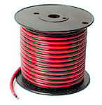 to make the boxes weatherproof. When buying zip cord, search the
Internet and compare prices. They vary widely, as do the shipping
costs. I bought mine at www.hamcity.com. Some
dealers were asking twice as much for the same item.
to make the boxes weatherproof. When buying zip cord, search the
Internet and compare prices. They vary widely, as do the shipping
costs. I bought mine at www.hamcity.com. Some
dealers were asking twice as much for the same item. Anderson
Power Pole connectors. These use the same size plastic housing as do
the 30-amp connectors many of you may be using to provide DC power to
your communication radios and accessories. The only difference is
that the metal inserts will accommodate 10-gauge wire rather than 14-
and 12-gauge wire.
Anderson
Power Pole connectors. These use the same size plastic housing as do
the 30-amp connectors many of you may be using to provide DC power to
your communication radios and accessories. The only difference is
that the metal inserts will accommodate 10-gauge wire rather than 14-
and 12-gauge wire. and 10 gauge wire that is ideal for placing in the power line between
the batteries and the charge controller. I have replaced the included
40 amp blade fuses with 30 amp fuses and will probably down size them
further. Our panels will produce less than half that amount of
current, and the charge controller will handle up to 30 amps.
and 10 gauge wire that is ideal for placing in the power line between
the batteries and the charge controller. I have replaced the included
40 amp blade fuses with 30 amp fuses and will probably down size them
further. Our panels will produce less than half that amount of
current, and the charge controller will handle up to 30 amps. around for prices, as they vary widely. Don't be fooled by lower
prices that don't include the meter.
around for prices, as they vary widely. Don't be fooled by lower
prices that don't include the meter.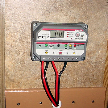 on the back side and bolted the ceramic tile and charge controller to
it. A piece of trim board was fastened below the ceramic tile and
screwed to the backing board to help share the tile's weight and
additional stresses placed on it while on the road.
on the back side and bolted the ceramic tile and charge controller to
it. A piece of trim board was fastened below the ceramic tile and
screwed to the backing board to help share the tile's weight and
additional stresses placed on it while on the road.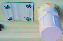 With
a hole to cover and limited resources in my shed, I decided to use a
piece of aluminum from a gutter pipe to cover the hole. After
applying a liberal amount of silicone caulk to the back side of the
patch, it was screwed into place.
With
a hole to cover and limited resources in my shed, I decided to use a
piece of aluminum from a gutter pipe to cover the hole. After
applying a liberal amount of silicone caulk to the back side of the
patch, it was screwed into place. an
hour the three panels provided 14.3 volts (limited by the charge
controller) and 9.4 to 10 amps, depending on the sky conditions. New
panels typically produce about 10% more than their specified amperage
rating, and these are no exception. Individually, they produced about
4.4 amps. The two batteries were already fairly well charged when the
current was applied, so they were not taking the full output the
units could have produced. The charge controller was limiting the current.
an
hour the three panels provided 14.3 volts (limited by the charge
controller) and 9.4 to 10 amps, depending on the sky conditions. New
panels typically produce about 10% more than their specified amperage
rating, and these are no exception. Individually, they produced about
4.4 amps. The two batteries were already fairly well charged when the
current was applied, so they were not taking the full output the
units could have produced. The charge controller was limiting the current. mounts
from wood. "Keep it simple, keep it cheap, make it work"
has become my motto.
mounts
from wood. "Keep it simple, keep it cheap, make it work"
has become my motto. a
wing nut. This arrangement did not tighten enough to "lock"
the stands into position with the wing nuts, but it provides a
swivel point. Triange-shaped pieces were cut from flakeboard siding,
stained and attached at the stand's lower corners to add additional stability.
a
wing nut. This arrangement did not tighten enough to "lock"
the stands into position with the wing nuts, but it provides a
swivel point. Triange-shaped pieces were cut from flakeboard siding,
stained and attached at the stand's lower corners to add additional stability. pegs on each side of the stand's crossbar on the bottom kept the
stand from moving either forward or backward. In addition, short
ropes between the stakes kept the stand from coming off the ground
due to wind. Other tie points can also be used. In case of an
imprending storm with possible high wind gusts, the panels can
quickly be folded for storage.
pegs on each side of the stand's crossbar on the bottom kept the
stand from moving either forward or backward. In addition, short
ropes between the stakes kept the stand from coming off the ground
due to wind. Other tie points can also be used. In case of an
imprending storm with possible high wind gusts, the panels can
quickly be folded for storage.