GPS
Tracker for APRS - Summer 2001
 |
The
GPS Tracker I made works very well and was so easy to
build. The only problem I had was that I could never find
any GOOD web pages about GPS Trackers. So I decided to
do my best to make my own and explain everything about
building and operating one.
Task
1:
The
first thing you need to decide before you build a GPS
Tracker is whether or not you want to use APRS with your
tracker. I'd recommend that you do use APRS with yours.
It's the only way to actually see where you and other
stations are.
Task
2:
The
second task to do is decide on the hardware you will be
using. You will need a total of 3 main things to compose
your tracker, 1. Radio, 2. TNC, 3. GPS. The picture below
is of the inside of my GPS Tracker.
The
radio you choose is your choice. Handhelds and mobiles
are both fine for trackers. The main idea of a tracker
is to have a gps, tnc, and radio all in one small box
so you may want to go with a handheld. Any handheld will
work as long as it has external microphone and speaker
jacks. You also want to be able to power your radio with
12V DC so it might be wise to choose a radio that can
operate on 12V DC. (I've seen some that are 7.5V DC)
The
next thing you need is a TNC. The only TNC I'd recommend
is the Kantronics KPC-3+. The only reason this is the
only one I recommend is because it's the only one I've
used. From my experience it is very easy to use and configure.
It is also small in size.
The
last thing you will need is a GPS. As you probably know
there are many GPS's to choose from. It took me about
a week to look through them all and decide which one I
wanted. I finally chose the Garmin GPS-35. I chose this
one for 2 reasons. One, I don't have a high budget and
two, I only need the GPS for a tracker. The GPS-35 look
like a GPS antenna. It has the GPS built in. That eliminates
the need for an antenna . Also, some people use there
GPS for other things such as hiking. This GPS DOES NOT
have a screen on it. It inputs everything right into the
computer. So I saved a lot of money buying a GPS that
did not have a screen and was built into and antenna.
I believe retail price for the GPD-35 is about $150. The
picture below is the GPS-35.

Here's what I used:
TNC: Kantronics KPC-3+
RADIO: Icom T2H Sport
GPS: Garmin GPS-35
Task 3:
Now
that you have your radio, tnc, and GPS, we can get to
the fun stuff assuming that you've tested the radio, tnc,
and GPS to make sure they work. (Go to the bottom of this
page to get a GPS program that will SHOW you that it works.)
The
next thing to do is find a box to put it all in. Some
people use ammo boxes, battery boxes, waterproof boat
boxes, and I used a small cheap tool box. You want to
make sure that everything will fit and that's including
cables, voltage regulators, and a lead acid battery (if
you want one).
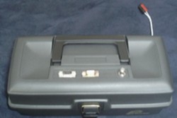
Now
you need to get the all the connectors and cables to make
everything work together. Look at the picture below to
see what I have on the top of my tracker. There are 2
DB-9 connectors for the GPS, and computer, and a BNC connector
for the antenna. I just drilled and used a file to shape
the holes for the DB-9's to fit into. The good thing was
that the box is hard plastic so it is relatively easy
to file and drill into.
As you will see in the picture below, the connectors on
the top of the tool box are just extensions to the connectors
inside. For example, the DB-9 on the right just extends
the connector on the back of the TNC so the computer cable
can just plug into the top of the box rather than inside
of it. It is the same for the GPS. The DB-9 has only 4
wires; 2 go to the TNC, 2 go the terminal strip for power.
So the connectors also just make everything neater. The
whole idea of having a track like this is so all you have
to do is plug in your computer, power, and GPS into the
top of the tracker.

Assuming you have all of your connectors mounted on your
box.
The
next thing to do is attach all of your wires. This is
kind of hard to explain but very easy to do. Below is
a wiring diagram of the wiring between the DB-25 computer
port on the Kantronics KPC-3+ and the DB-9 on top of the
tool box. The reason there is a DB-9 is because all new
computers use DB-9 connectors rather than the old DB-25.
I bought a DB-9 extension cable from Radio Shack that
has a DB-9 female on one end (to computer) and a DB-9
male (to DB-9 on top of box).
Next
is to wire the radio port of the TNC and the GPS port
on top of the box.
To
wire the DB-9 radio port to the radio look at the wiring
diagram below.
So
now you should have your TNC wired to the the DB-9 computer
port on top of the box and to the radio speaker and microphone
plugs. Next we are going to wire up the GPS.
Im
going to show you what I did for the wiring. I think it
is the easiest way to wire a GPS to the TNC. *NOTE: The
fallowing diagram and paragraph are only for the KPC-3+.
They will NOT work with the KPC-3.
The other DB-9 on the top of the box is the GPS connector.
On the end of the cable going to the GPS I added a female
DB-9 connector. Below is a diagram of the wiring for the
GPS port on the box. Note the text on the left of the
diagram. It says where the wires from the GPS connect
to the KPC-3+. They connect to the DB-9 RADIO port of
the KPC-3+.
Task
4:
All that is left is to power everything. As you can see
in the picture below I power everything via the terminal
strip mounted on the left side of my tracker box. I have
wires from the radio, tnc, and DB-9 GPS port connecting
to the terminal strip. I also have about 6 inches of wire
running from the terminal strip to outside of the box
for the main power input. If you look at the specs of
the TNC, GPS, and radio you will notice that they don't
pull anymore than about 5 or 6 amps total. Most cigarette
lighters in cars can handle from 15 to 20 amps. So I just
added a cigarette lighter plug on the end of my wires
going into the GPS Tracker.

THAT'S IT!!! You've finished building it. Easy wasn't
it? Now is the easy part. Configuring it all to work together.
Task
5:
Configuring
The
first thing to do is make the TNC recognize that there
is a GPS connected to it. So first you need to power up
everything and make sure the GPS in a location where the
satellites can see it (on a window seal). Next open a
Packet terminal program such as WinPack and type the fallowing
commands when you're in command mode. Do not type the
parentheses, they are just to show that, that is a command
to type.
<GPSPORT
4800 NORMAL CHECKSUM>
<GPSHEAD
1 $GPRMC>
<GPSHEAD
2 $GPGGA>
<GPSTIME
VALID RMC>
<CD
SOFTWARE>
<CONMODE
Converse>
<LTP
1 GPSLJ V RELAY,WIDE2-2>
<LTP
2 GPSLJ V RELAY,WIDE2-2>
<BLT
1 EVERY 00:03:00 >
<BLT
2 EVERY 00:03:05>
Those
are all of the commands NEEDED to get the GPS and TNC
to talk to recognize each other.
So
now what you have done is told your TNC to transmit the
$GPRMC string every 3 minutes and the $GPGGA string every
3 minutes and 5 seconds. The GPS puts out many different
NMEA strings and loads them into the TNC buffers. The
TNC transmits the strings according to the BLT command.
Task 6:
The
final step to making your tracker is using it with WinAPRS.
The only APRS program that I have used is WinAPRS. There
really isn't much to it though. First power everything
up and give the GPS a few minutes to aquire the satellites.
Now you need to turn your radio to the national APRS frequency
of 144.39. Next open up WinAPRS and put in you callsign
and other necessary data. Then you need to select the
baud rate of the TNC in the SERIAL PORT window of WinAPRS.
Now just select the map of your area and click OPEN VHF
TNC under the CONFIGURATION menu of WinAPRS. You should
start seeing other station popping up on the map including
you.
Thats
it!! Your finished. I hope you like your new GPS Tracker
as much as I do.
|

 Proud
to be member #259 of the
Proud
to be member #259 of the