Ameritron
AL-80A - Summer 2003
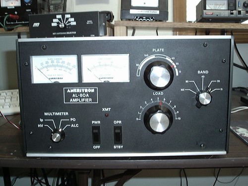 |
The Ameritron AL-80A uses a single 3-500Z triode to produce
over 1KW of power with only 65 watts of drive.
I purchased it in the beggining of July 2003. It had several
problems when I got it. The tube was bad, a VHF parastitic
had occurred, causing several components to fail. As far
as mechanically, there was only one problem. The plate tuning
capacitor has a plastic coupler that connects it to the
knob. This coupler was cracked were it slipped over the
capacitor rod, allowing it to slip.
What
is a VHF Parasitic? This is when a VHF voltage causes
an self-resonant fly-wheel type occilation in the tube.
When this happens, all hell beaks loose and many things
make a day turn bad. There are two things that need to
be done to solve this problem. First, the Q of the VHF
self-resonant circuit needs to be reduced, and to reduce
the VHF voltage-gain of the amplifier stage. To solve
this problem so that a parasitic is less likely to occur,
the anode and cothode self resonant frequencies need to
be farther apart by reducing inductive reactance. This
is done by shortening lead length and tuning it out by
bypassing the grid to the chassies by using small capacitors.
This increases the self-resonant frequency of the grid
circuit to point where the tube will have less amplifing
and osccilation ability.
Below
is a list of all the things I did to the amplifier with
an explanation.
1) Replace the VHF Parasitic Supressor
2) Add a step-start circuit
3) Add an additional capacitor to the anode choke
4) Add fast T/R switching
5) Adjust filament voltage to 4.8VAC
6) Add diodes across meter shunt resistors for glitch
protection
7 ) Add rectifiers across HV filter caps.
8 ) Replaced the cathode bias zener dipode with several
rectifiers.
1*
I replaced the original VHF parasitic supressor which
was a 100ohm resistor with a inductor around it, with
Nichrome wire and two 100ohm resistors in parallel. The
Nichome wire has an extremely small amount of resistance
and handles large current and voltage being close to 22AGW.
2*
The step-start circuit I added used a simple 10A 120VAC
DPDT relay and 2 25ohm 10watt resistors.
Current went through the resistor and after about 1 second
the voltage was high enough for the transformer to produce
120V. This closed the relay contacts allowing current
to bypass the resistors. This simply protects the circuity
and especially the filament from voltag skikes and current
inrush.
3*
The original capacitor was .001uF 7.5V. I added another
capacitor to make it 10pf.
4*
Even though I dont do QSK often I do use Vox during the
heat of a contest. The amplier does switch to transmit
pretty fast when I key down. Thats not really the issue.
The issue, is that the T/R relay is hot switching. In
other words, the radio is keying down and putting power
out before the amp relay can even think about switching
the relay. So the amp relay is switching while 100 watts
is on it, which is very bad for the contacts. You can
tell by seeing a SWR spike when you first key down. To
fix this, I made an entire new circuit board that not
only contained the fast T/R switching, but the electronic
cathode bias switching also. There are two different relays
for the fast T/R switching. One input and output. The
output relay is a high speen Kilovac HC-1 vacuum relay,
while the input relay is a RF reed-relay. This will insure
that when the tranceiver Xmit is brought to ground, the
amp will switch the relays before power is put through
it.
5*
One of the most important things is filament voltage.
A 3-500Z has a minimum of 4.8V with a max of 5VAC. If
there is a 3% increase above 5VAC, it will decrease the
life of the tube by one half. I measured the voltage of
mine and it was 5.2volts, which is way to high. I replaced
the filament wire with 24AGW and added some resistive
wire to one end. Using smaller wire is much easier then
trying to find a .25ohm resistor. This brought it down
to a perfect 4.8VAC. Even worse than 3% higher voltage
is a under voltage. That will literally kill the tube
in a very very short time.
6*
If there is ever a glitch, where the HV arcs to ground,
the meters will be blown out of the panel. I added some
200A PIV diodes across the meter leads to that they would
be destroyed rather than the meters.
7*
The next thing I did was add rectifiers across each HV
filter cap. Electrolytic caps are detroyed very easily
be a reverse voltage, especially that high. So if the
HV were to ever arc to ground, the diodes would be destroyed
while the capacitors are beeing nicly bled down by their
resistors.
8*
The next thing to do was replace the 7.5V 10watt cathode
bias zener diode with a string of rectifiers in the foreward
operating position. This not only allows adjustment to
75mA of plate current wich is optimum, but also helps
retain 5v of cathode bias voltage. My fast T/R circuit
contains a transistor used as a switch to auto switch
the bias when transmitting.
|

 Proud
to be member #259 of the
Proud
to be member #259 of the