
|
|
01/02/07 |
       
|
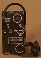
The AN/PRC-90 Legacy
Alan D. Tasker WA1NYR ( [email protected])
photo by Petty Officer 2nd Class G. J. Barry, U.S. Navy.
A. Introduction In the annals of US Military Portables, only four types have produced more than one "offspring," at least by my definition (A production unit that offered some significant difference from its production unit parent that was not just an MWO). These four are as follows.
The following discussion will explain to some degree the story of the AN/PRC-90, the first tri-service rescue radio, and additional rescue related products, production of which began at GTE-Sylvania in Needham, MA starting sometime in the mid-nineteen sixties. According to Jane’s, the approximate number of PRC-90 units of all types ordered is well over 50,000 units. Many are still in use today, sometimes even being preferred over the supposed replacement (AN/PRC-112). This attests to the excellence of these older designs. Ref #4, 5
B. Background In the 1965 period, GTE-Sylvania had produced the smallest single frequency military rescue radio ever, the AN/PRC-63 (Navy contract). They used modular techniques along with a space saving super regenerative receiver, a new small 14-Volt mercury battery (BA-1568) that could be enclosed in a waterproof compartment with a screw on cover, and possibly the first military use of what we now call the "rubber duckie" antenna, although thinner than most. However, the experiences in the Vietnam conflict were proving the need for at least a two-frequency unit. Adapting the circuitry of the PRC-63 for this task would not work for the following reasons.
C. The Basic AN/PRC-90 Design This led to the basic design principals of the PRC-90, which were……
Modular construction was again used. The internal module placement is as follows. All descriptions below assume that the unit is sitting with its front side down (i.e. as in on top of a table), that the antenna is pointing away from you, and that the back cover has been removed. Once this is done, it is easy to see that the main interconnect within the unit is a long, thin, vertically oriented printed circuit board running from the top to the bottom, and centered half way between the right and left sides. The two receiver modules are mounted horizontally, one above the other, and plugged into this central board toward the bottom left, opposite the battery compartment (which would be on the bottom right). There is a smaller module underneath them that amplifies the receiver audio, and the Tx audio/modulator module is on top of them, making it a four-module stack. The two receiver modules are also mounted one on top of the other, and plugged into the central board on the top right, opposite the three controls (channel switch, PTT switch, and MCW switch). Underneath them is the Tx/Rx switching board. One neat concept introduced here was the frequency selector switch. It can not leak because no moving parts penetrate the case. The switch uses an external permanent magnet that moves with the switch rotation, and this causes internal reed switches to close at the proper position (similar to how an RT-60 frequency selector switch works). Ref #3
The basic specifications are as follows. Ref #4 1) 400-mW output power in voice mode, 243 MHz or 282.8 MHz, AM. There is some discussion about a patented circuit that GTE-Sylvania employed in this unit, perhaps acquiring it originally from NCR. By examining the circuit diagrams, it would appear this patent, if related to a single circuit, was used to effect the receiver design. This single conversion superhet employs only five transistors in the main receiver module. The function of these is as follows.
This is an extremely compact design, even for single conversion.
Manufacturers,
Ref #1, 4, 7 Known manufacturers include.
NSN 5820-00-782-5308LS
D. Cost Saving Efforts Although a very effective design, the PRC-90 was expensive to produce. It was clear that in order to save money, major internal changes would have to be made. Chief among these were the following.
It is not clear to me who accomplished the design changes. It is known that both ACR and OAI manufactured the first cost reduced version, the AN/PRC-90-1. Ref #1
E. The AN/PRC-90-1 This unit was produced using cases originally made for the PRC-90 production, and containing letter engraving for that unit. However, in the 90-1, the MCW function had been eliminated and replaced with a high power beacon function, so paste strip overlays were used as appropriate to change external labeling.
Internal Changes Both the receiver and transmitter were reduced in size to fit as much as possible on a single conventional PC board, and each is located in the same relative positions as discussed above. In the ACR design, the receiver made use of the LM1868 AM receiver chip, certainly a great space saver. There was, in addition, a small audio amplifier module located on the central board. The transmit modulator used the LM386 amplifier chip (located on the central board) to drive the modulation transformer. I assume the OAI design is similar if not identical. There may have been other changes, but with the exception of the PRC-90 modules, I do not have any schematic diagrams for any of the radios discussed in this report. If some come my way, I will see if there is anything else that pops up as significant. Ref #1
Antenna Redesign
Both ACR and OAI take credit for changing the ¼ wave antenna into the much more effective ½ wave type. It should be pointed out here, however, that ½ wave designs were nothing new to ACR. The manual for the AN/URC-10/RT-10 (The URC-10 is a separate battery version of the ACR designed RT-10) states that there are two types of units in the field, those with ¼ wave antennas and those with ½ wave antennas.
The 90-1 ½ wave has a base matching section to transform the high antenna impedance to the radio’s output impedance (50 Ohms assumed). Above that is a springy section just long enough to allow the antenna to fold around the top of the radio for storage. Lastly, above that is a telescoping section.
Specifications, AN/PRC-90-1 Ref #3, 4, 7
F. THE AN/PRC-90-2
It would appear that the only changes contained in this unit as compared to the 90-1 are as follows.
In order to accomplish the latter, I am assuming the matching section is incorporated inside the unit in discrete form. The PRC-90-2C is apparently a non-rescue frequency version of the 90-2. Known manufacturers include the following. Ref #1, 4, 7
-2, NSN 5820-01-238-6603 -2C, NSN 5820-01-338-3036
Web Addresses Where the AN/PRC-90 is mentioned http://home.earthlink.net/~aircommando1/castle.html http://www.pbs.org/wgbh/pages/frontline/gulf/voices/2.html http://www.ntsc.navy.mil/code1/air/ast/devices/9c1.jpg (picture) http://www.seawolf.org/scrmbl03.htm
Manuals, PRC-90 Series
T.O. 31R2-2PR-101
G. The AN/PRC-90A Other than being a haze gray in color as opposed to the green of other units, and having an attachment that essentially enlarges the target size of the PTT button, there appears to be no other differences between this and other models. The Navy ordered a small quantity of these to provide communications for wearers of HAZ-MAT suits. These suits had their own internal headphone and microphone, so some sort of interface had to be designed and built. This interface device is called the HMF-3 acoustical coupler. It clamped to the front of the PRC-90A, and pressed its small speaker to the 90A’s microphone. It also had a plug to connect to the 90A’s earphone jack. Powered by small batteries, this coupler amplified and buffered both the Rx and Tx audio signals between the 90A and the audio components of the suit. The only manufacturer of these components seems to be OAI. Ref #1, 2
H. PRC-90 "T" Units Both the PRC-90 and the PRC-106 (see below) were bought in a training version, that is, crystaled for training frequencies instead of rescue ones. Generally, this was 251.9 MHz and 236 MHz. The designation was changed to AN/PRC-90T, for example, to indicate this change. In addition, training units are generally painted yellow so there would be little likelihood of grabbing the wrong unit in a pinch. Ref #7 90T, NSN 5820-00-469-5658 90-2T, NSN ?
I. THE AN/PRC-106
The AN/PRC-106 is similar to an AN/PRC-90 except its two channels are 121.5 Mhz and 243 MHz. In order to accomplish this, the original 90 design of two separate receivers and transmitters had to be used. The beacon function has been eliminated from the rotary frequency selector switch. However, that function is now available on either frequency by pushing the top mounted switch (which was the MCW function switch in a PRC-90). There is a new feature provided that was not used on the original 90. Each transmitter contains a detector circuit that feeds actual transmitted audio to the earphone for Tx sidetone.
Manufactured by ACR, OAI, and C-RAN since 1974 for the AF, DEA, and probably others, it has the following specs.
Manuals
J. Para-Rescue Units, the AN/PRC-103 and the AN/PRC-125 Air Force Produced since 1976 by C-RAN, the AN/PRC-103 is an Air Force para-rescue radio. It is a PRC-90 type with the following changes.
Internally, the construction is similar to the original 90, i.e. two receiver and two transmitter modules, etc.
Manuals
NSN 5820-00-009-2740-LS
Navy
Produced by OAI, the AN/PRC-125 is the para-rescue radio for the Navy. Although the unit is similar in size to those discussed above, and although it uses the same battery, the only control on the main body is very different (although it still uses the magnet/reed switch arrangement), and the link back to GTE becomes a bit tenuous here. The frequency selector/off switch is a side mounted slide type as opposed to the rotary type on the above units. The antenna, volume control, PTT switch, and earphone jack are on a remote speaker/mic that connects to the radio by means of a 36" cable. The radio has a jack on the top for this purpose. This set is stored in, and meant to be used with the LPU-28/P Life Vest. The speaker/mic mounts to the vest (Velcro) in such a way that the wearer’s chin can be used to depress the PTT switch. Internally, there are a series of plug-in printed circuit boards (right to left orientation) that plug vertically into a motherboard located just behind the front panel. The circuitry is primarily discrete transistor in nature.
Manuals
K. The AN/PRC-96 Lifeboat Radio In 1972, GTE received an order from the Navy for 1200 Lifeboat radios, AN/PRC-96. Ref #4. This was a unit similar in some respects to the PRC-106, i.e. it transmitted and received on either 121.5 or 243 MHz. The main difference was the use of "D" cell diameter Lithium batteries (slightly longer than two "D" cells in series). At two per radio (3 Volts/cell), the terminal voltage was only about 6 Volts as opposed to the 14 Volts used in the other designs. This would have necessitated many circuit design changes compared to previous designs. One wrinkle was the fact that Lithium batteries are not allowed in a submarine environment. This was accommodated by adding a sleeve (screws in to the existing battery compartment and uses the existing battery cap) to allow four "D" cell alkaline batteries to fit for these applications. "D" cells have a larger diameter than the battery used in the other GTE designs, so the case dimension of the PRC-96 was necessarily larger in the thickness direction, thus leading to many physical changes. There is only a combination speaker/mic, and the other controls are mounted on the top of the unit as opposed to the front. A battery test meter or test pin was added to the backside. Internally, there are eight small circuit boards that are soldered into a motherboard. Some ICs are employed, but the soldered nature of the boards and lack of circuit diagrams makes investigation difficult. GTE, tiring of market pressures at this point, sub-contracted production to C-RAN Corporation. Specifications
Manuals
L. Epilogue All of the above products, with the possible exception of the AN/PRC-90A, remain in use today, coming out of service as they fail. The supposed replacement for the above for normal rescue duties, the Motorola AN/PRC-112, is itself heading for replacement. A number of special PRC-112 units with internal GPS, called the Hook-112, have been acquired for interim duty in the hot spots of the world. Meanwhile, Boeing won the contract award for CSEL (Combat Survivor Evader Locator), the next step. They awarded the radio contract to Racal, and its nomenclature is AN/PRQ-7. It is, however, an expensive set, as it operates on VHF and UHF guard channels as well as 600 MHz, being capable of transmitting both voice and data, and having an internal GPS capability. Rumor has it that a contract has been awarded to Tadiran for a less expensive set. There does not seem to be any information on the web about this yet.
M. References 1. - Observation 2. - Manufacturer’s Literature 3. - The Technical Manuals for the individual units 4. - Jane’s Military Communications, 1981 and/or 1994-5
Go back to Military home page Go back to Home pageWB4TUR 2/2000
W4XE 2/2002
|
This site was last updated 01/02/07

