The next step is to install the reflector elements. During element assembly you will work with the aluminum alloy wire that is supplied on two spools, one for the reflector loops and one for the driven element loops. It is solid wire, about 1/16 inch in diameter. Eye protection is recommended because the wire is like a big spring. Once you unreel it from the spool it will snap back with a lot of force if let go and could potentially cause some harm if you are not careful. If you can have some help during this phase, it will save some time. It is possible to do this by yourself ( I have) if planned carefully. If you have a helper, he/she needs to hold one end of the wire at all times so it does not snap back. If released, the wire will coil back up and make it very difficult to feed through the wire holders.
Element assembly begins with measuring and cutting to length the 20 meter reflector loop. Cut each wire an inch or two longer than needed to allow for mistakes. The aluminum alloy wire is very strong under tension, however, it breaks if bent back on itself or in too tight a loop. If you make a mistake bending the attachment loops, don't unbend it, just cut that portion off and start over. Use long nose pliers and bend the wire gradually to form the loop as shown in the instructions. If you see any hint of cracking on the surface of the wire, start over. Some practice in bending the wire before hand is recommended.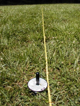 |
 |
|
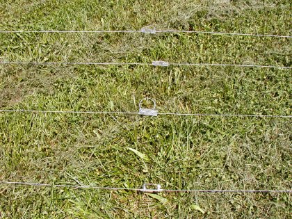
| Measuring
the wire lengths for each element. You should use a 100 foot tape
measure and pull the wire tight when measuring and cutting. |
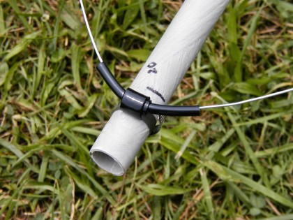
The wire holders allow the wires to move freely when the spreaders flex in the wind. |
Before unreeling and cutting the 20 meter loop, bend the first attachment loop. Attach the plexiglass insulator to the loop you just made using the stainless steel nuts, bolts, and washers. Make sure the wire is between the two washers as shown in the instructions and tighten it enough to hold it in place. Final tightening will be done after the reflector elements are all done. Also do not overlap the wire, bend it exactly as shown in the instructions or it will break at the point of overlap after the nuts are tightened. Next, take note of where the paint mark (blue or red) is on the hub. You must string the wire so that when you are done, the plexiglass insulator will be centered under the paint mark. Take the unbent end of the wire and feed it through a 20 meter wire holder located under the paint mark, then work your way around the spreaders, feeding the wire through the outer most wire holders. Don't let the wire coil up during this process or you will wind up with a kink and a potential breaking point. Once you have the wire threaded through all four wire holders, you can let go of it. Cut off any extra wire and bend the attachment loop on the other end of the wire. At this point you will need to loosen one of the wire holders to allow enough slack to attach the free end of the wire to the plexiglass insulator. Once the second end is attached, to the insulator, it should be approximately centered between the ends of the adjacent spreaders. Move the loosened wire holder back into place to take the slack out of the wire but do not tension it yet. At this point you have completed the assembly of the 20 meter reflector loop.
 |
||
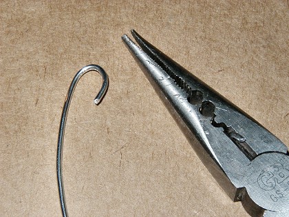
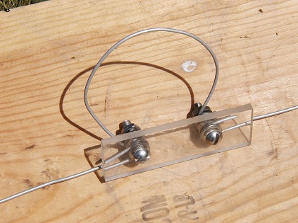
| A properly formed attachment loop. |
Repeat this process for the 17, 15, 12, and 10 meter reflector loops. Bend the attachment loop, unreel the wire, cut it to length, attach the insulator to the looped end of the wire, feed the wire through the wire holders, bend the second attachment loop on the free end of the wire, loosen a wire holder, attach the free end of the wire to the insulator, reposition wire holder to remove slack, and center the insulator between the ends of the adjacent spreaders.
Now a side note...
The wire installation process can be completed by one person. To do this, here is the procedure I have used.
First, I drive a large nail (I use pole barn nails found at Lowes) into the ground. I locate the nail so that when you unreel the wire, the loose end will be close to the spreader which is at this point assembled and laying on the ground. Next I clip a 100 foot tape measure to the nail and reel out enough tape to measure the length of wire needed. Next, take the spool of wire and bend the attachment loop with needle nose pliers and hook it to the nail in the ground. Then insert a large screwdriver through the hole in the spool of wire and walk along the tape measure toward the spreader unreeling the wire as you go. When you have enough wire unreeled, pull it and the tape measure tight and cut the wire as described above. At this point you will need something heavy to lay on the wire temporarily while you work on the end hooked to the nail. I use a few bricks for this purpose. Next, unhook the wire from the nail and attach the plexiglass insulator to the looped end of the wire.
I use a vise grip plier (locking jaw pliers, preferably a large pair) to hold down the loose end of the wire (to prevent it from coiling up) while threading the wire through the wire holders. Next, clamp the vise grip onto the plexiglass insulator, on the end opposite to where the wire is attached. The vise grip needs to be tight enough so you can drag it on the ground with the wire to keep the slack out, but not so tight that the plexiglass becomes cracked. Drop the vise grip plier on the ground and pick up the free end of the wire under the bricks. Pull the length of wire over to the spreader and thread the wire through the wire holders (as described above) while keeping tension in the wire with the weight of the channel locks holding the other end of the wire. Once the wire is threaded through all four wire holders, bend the attachment loop on the free end, remove the channel locks and attach the wire to the insulator. This completes installation of the wire. Repeat this process for all of the other wires.
End of side note...
Once you have all five reflector loops installed, check to make sure all of the loops are evenly spaced on the spreaders and tension the loops so that the spreaders have a slight bow to them. Then tighten all the nuts on all five of the plexiglass insulators. A little advice here... While the element is laying on the ground, the wires will have more tension in them than when they are in the air. If you put too much tension in the wires, it can cause problems later that will eventually break a wire. I shoot for about 1 foot of bow in the spreader when it is laying on the ground. This foot is the distance from the ground to the end of the spreader with the element laying level on the ground. More tension than this will put excess stress on the wire and wire holders under high wind loading and will eventually break a wire. Less tension will cause too much slack in the loops once the antenna is in the air and the loops could potentially flap in the breeze and touch each other and lead to breakage due to excess flexing of the wire around attachment points. A good indication that you have the tension right will be seen once the antenna is in the air. I have found that with high wind loading and with the reflector pointed into the wind, it can snap inside-out, or stay bowed in the opposite direction in gusty wind. If the reflector snaps back easily, you have the tension about right. If it stays inside-out for long periods of time, the wires are too tight. If you have guy wires at the top of your tower his condition can cause interference between the guy wires and the ends of the spreaders. The driven element is less susseptible to this when the wire are tensioned properly. It is stiffer since all of the loops are tied together at the balun.
 |
 |
|
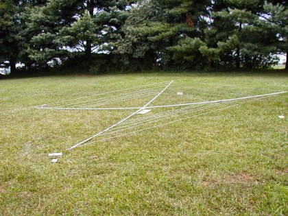
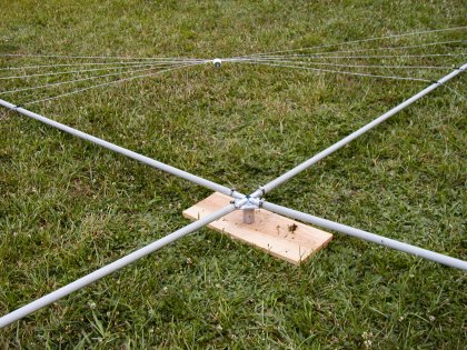
| The completed reflector with wires tensioned and shorting stubs installed. |
Once installed, the spacing between the elements should be checked and adjusted for even spacing. |
Once all of the elements are tensioned, the reflector shorting stubs are installed on the plexiglass insulators. I find that the stub lengths given in the instructions work just fine. A second set of washers and nuts is used to secure the shoring stubs. Although not as critical as the other attachment points, the same guidelines for wire bending and placement should be followed. After everything has been properly tensioned and tightened, all of the shorting stubs should be centered under the paint mark on the spreader hub.
 |
 |
|
| The completed reflector with shorting stubs installed. |
The reflector shorting stub hardware. |
Assembly of the driven element is much the same as the reflector. The major difference is in the order of installation of the loops. Following the recommended antenna feed point configuration, all five driven element loops are fed in parallel through the supplied 2:1 balun. This requires that the 15 meter loop be installed first, followed by the 10, 12, 17 and 20 meter loops. The ten meter loop should attach to the balun closest to the body of the balun, and the 20 meter loop should be the farthest from the body of the balun, with the rest of the wires in band order from inside to outside. The balun is installed with the coax connector pointing toward the ground and the wire mounting stubs pointing up. Each wire should be placed between washers and the entire assembly tightened once all of the wires have been attached. On the driven element, a bit more effort is needed to position the feed point in the center of the bottom of the loop. The balun should be under the paint mark on the spreader hub. Partial tensioning of the wires of each element as it is installed helps keep the balun in place. Otherwise tensioning of the wires on the driven element is done the same way as the reflector.
 |
 |
|
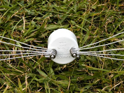
| The completed driven element with balun installed and wires tensioned. |
With all of the driven elements installed, the wires on the balun should be in the following order, 10, 12, 15, 17, and 20M starting closest to the body of the balun. |
With both elements assembled, check that all the loops are centered and all the wire holders are tight. The clamps on the wire holders are not as heavy as the other hose clamps. They do not have to be super tight to stay in place and can be over tightened to the point of breaking if you get "too enthusiastic" about making sure they are tight.
 |
||
| The completed driven element with the balun and wires tensioned. |
|
Once the elements are assembled, the boom to mast plate is installed on the rotator mast and the boom is centered with the paint marks pointing towards the ground. Pre-marking the center of both the boom and boom-to-mast plate before installation makes this step easier. The nuts clamping the boom are just finger tight at this point. Each element is installed by inserting the hub into the end of the boom and securing it with a bolt.
When doing this step by myself, I have found it to be a big help to polish the spreader hubs and the inside of the ends of the the boom with steel wool and then apply a little lubricant like WD-40. This makes the hub slide into the boom easily. If you have a helper for this step you may not need to do this. Once the elements are installed, the antenna is leveled and the boom to mast clamp nuts are tightened. Be careful when tightening the boom clamps. The boom is thin walled aluminum and will collapse if the clamps are overtightened weakening the boom.
With the antenna assembled all that is left is connecting and securing the feed line and rotator loop. I weather proof the coax connection with vulcanizing tape and seal the potted side of the balun with R.T.V.
 |
 |
|
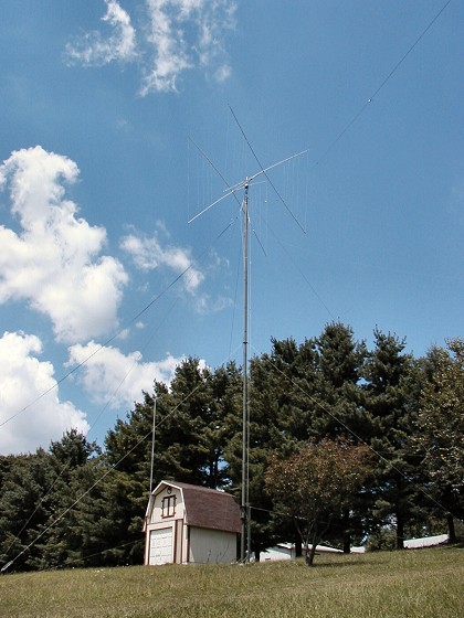
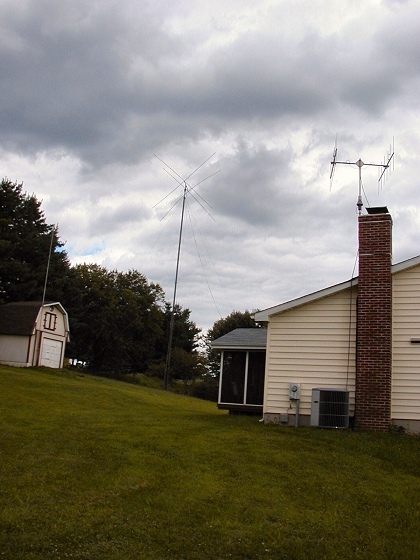
| The completed installation on 60 feet of AB-577. |
|
I have found that following these procedures results in an installation that is correct the first time with no other adjustments needed. The antenna has good front-to-back, signals virtually disappear off the ends of the elements and the standing wave ratio is good on all bands. Click here to see the SWR plots for each band. I originally had some concern about running 1500 watts through the supplied balun, but have not had any problems doing so. With an SWR less than 2:1 on any frequency on the 5 bands, my amplifier puts out the legal limit.
This project requires some work, but with proper planning it can all be done in one weekend by one person. I have successfully assembled this antenna and made repairs to it in this time. I did however, learn some of the lessons described above the hard way. So I hope you find this information useful if you are planning to purchase and install a LightningBolt quad.
One last thing ... The one weak point in the design of this antenna is the boom. The supplied boom is a 2 inch outside diameter thin wall aluminum alloy which will bend over time. The original boom on my antenna had a large set in it after two plus years in the air. This was most likely caused by an ice storm we had in December 2001 and was made worse by over tightening the boom clamps. The antenna survived the ice storm with no apparent damage (½ inch diameter of ice over a 24 hour period) but the boom had a noticeable curvature to it when I took it down for repair the following summer. Since then I have reinforced the boom by inserting a length of PVC pipe in the boom to stiffen it. I recently had the antenna down to replace a faulty rotator and found that the boom still was bending a little, most likely from wind loading.
The plus side of this is that replacement parts can be purchased from LightningBolt at a very reasonable price. Any of the parts supplied with the antenna, right down to the washers, can be purchased. LightningBolt makes a four element quad which has a heavy duty boom. You can buy a version of the two element quad which uses this heavier boom and allows the antenna to be upgraded to the four element version. I looked into doing this, however, the heavy duty boom nearly doubles the weight of the antenna. This does not lend itself to my installation so I tried reinforcing the boom with a PVC pipe to keep the weight to a minimum.
My quad sits on top of an AB-577. The AB-577 is a crank-up mast used by the military. It was available on the surplus market and has become a very popular item among hams in recent years. The performance of the antenna is excellent. I frequently receive unsolisited comments on the strength of my signal, even while running 100 watts. When I installed the quad in June 2001, I had 286 countries worked using only wire antennas. Since then, I have added 43 countries and have over 330 countries confirmed on CW and SSB.
I hope you have found this information useful. I welcome any comments you may have. Just drop me an e-mail from the link at the botom of the main page or at [email protected].
 |
 |