|
|
|
|
|
|
|
|
|
|
|
|
|
|
|
|
|
|
|
|
|
|
|
|
|
|
|
|
|
|
|
|
|
|
|
|
|
|
|
|
|
|
|
|
|
|
|
|
|
|
|
|
|
|
|
|
|
|
|
|

|
|
|
|
|
|
|
|
|
|
HOW TO CONSTRUCT AN EFFICIENT WIRELESS TELEGRAPH APPARATUS AT A SMALL COST.
From Scientific American Supplement, February 15, 1902
|
|
|
|
|
|
|
|
|
|
|
|
|
|
If you would like to read this article click on the heading above.
|
|
|
|
|
|
|
|
|
In early 2001 we found this web site on how to build a 1902 wireless station , this was before the word "Radio" was used. The station used
a Coherer receiver
which preceeded the concept of the crystal set.
The Transmitter used a Ruhmkorff coil which is basically the same as an automobile spark coil.
|
|
|
|
|
|
We contacted Dave Riley AA1A and sent him the Web page for this 1902 station asking him if he could
build one exactly as shown in the 1902 article. Dave has over 40 years of radio experience from bouncing
signals off the Moon to transmitting with lasers, so if anyone could do it he could.
|
|
|
|
|
|
|
In about three weeks Dave came up with a prototype station that could transmit across the room.
The original 1902 station could transmit about 1/2 mile over land and 2 miles over water.
|
|
|
|
|
|
|
|
|
|
|
|
Probably for the first time in the 21st Century
A communications concept from 100 years ago was up and working !!!
|
|
|
|
|
|
|
|
|
|
|
|
|
|
|
|
|
|
|
|
|
|
|
|
|
|
|
|
|
|
|
|
|
|
|
|
|
|
|
|
|

|
|
|
|
|
|
|
|
|
|
|
|
|
|
|
|
|
|
|
|

|
|
|
|
|
|
|
|
|
|
|
|
|
|
|
|
|
|
|
|
|
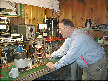
Dave in his lab doing his magic with the first spark prototype
using an automobile igniton coil.
|
|
|
|
|
|
|
|
|
|
|
|
|
Click to enlarge
|
|
|
|
|
|
|
|
|
|
|
|
|
|
|
|
|
|
|
|
|
|
|
|
|
|
|
|
|
|
|
|
|
|
|
Coherer
|
|
|
|
|
|
|
|
|
|
|
|
|
|
|
|
|
|
|
|
|
|
|
|
|
|
|
|
|
|
|
|
|
|

|
|
|
|
|
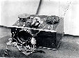
The finished Coherer receiver consists of four components,Coherer, door bell, relay, telegraph
sounder, and two batteries. The Coherer is a glass
tube with Nickle(95%) and Silver (5%) filings.
On receiving a signal the filings cohere
and conduct closing the relay which activates the telegraph sounder. At the
same time the door bell tapper contacts the coherer and de-coheres the fillings
for the next signal. Code could be received at about 12 words per minute.
The operator would decode the clicks of the sounder into letters and words.
|
|
|
|
|
|
|
|
|
|
|
|
|
|
|
|
|
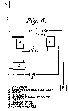
Coherer
Diagram
|
|
|
|
|
|
|
|
|
|
|
|
|
|
|
|
|
|
|
|
|
|
|
|
|
|
|
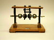
The Spark transmitter consists of a hand key, a brass stand for the arc, a Ruhmkorff coil and
a battery. The Ruhmkorff coil is similar to an auto ignition
coil, this was first patented in Germany
about 1850. This Ruhmkorff spark coil was donated by Fran K1JKV on Nantucket Island.
The Spark Gap coil came from a
house that was built expressly for the Marconi station in Siasconset
on Martha's Vineyard Island and was at one time in more recent years owned by an aunt of
Mary,
K1JKV's xyl. The hand key was donated by Jim K1ZJW, and from the over sized contacts it
appears to be an original spark key.
|
|
|
|
|
|
|
|
|
|
|
|
|
|
|
|
|
|
|

|
|
|
|
|
|

|
|
|
|
|
|

|
|
|
|
|
|
|
|
|
|
|
Spark Gap
Diagram
|
|
|
|
|
|
|
|
|
|
|
|
|
|
|
|
|
|
|
|
|
|
|
|
|
|
|
|
|
|
|
|
|
|
|
|
|
|
|
|
|
|
|
|
|
|
|
|
|
|
|
|
|
|
|
|
|
|
|
|
|
|
|
|
|
|
|
|
|
|
|
|
|
|
|
|
|
|
|
|
|
|
|
|
|
|
|
|
|
|
|
|
|
|
|
|
|

|
|
|
|
|
|
|
|
|
|
|
|
|
|
|
|

|
|
|
|
|
|
|
|
|
|
|
|
|
|
|
|
|
|
Rotary
Spark
|
|
Rotary Spark
at Poldhu
|
|
|
|
Marconi Magnetic
Detector, called a
" Maggie"
|
|
|
|
|
Spark Oscillator
|
|
|
|
|
|
|
|
|
|
|
|
|
|
|
|
****Hear the Rotary Spark as it****
sounded in 1903
|
|
|
|
|
|
|
|
|
|
|
Note: You may need to down load the Windows Media Player
to hear the spark gap. Please Click here.
|
|
|
|
|
|
|
|
|
|
|
|
|
|
|

|
|
|
|
|
|
|
|
|

|
|
|
|
|
|
|

|
|
|
|
|
|
|
|
|
|
|
|
|
|
|
|
|
|
|
|
|
|
|
|
|
|
|
|
|
|
|
|
|
|
|
|
|
|
|
|
|
|
|
Page 5 of 9
|


![[ 1 ]](w1aa_1p01.gif)
![[ 2 ]](w1aa_1p02.gif)
![[ 3 ]](w1aa_1p03.gif)
![[ 4 ]](w1aa_1p04.gif)
![[ 5 ]](w1aa_1p05.gif)
![[ 6 ]](w1aa_1p06.gif)
![[ 7 ]](w1aa_1p07.gif)
![[ 8 ]](w1aa_1p08.gif)
![[ 9 ]](w1aa_1p09.gif)