AF-67 Trans-citer
Classic K4MGS/WB4KDI "ELMAC" pre 1955 on the left; "MULTI-ELMAC" post 1955 on the right.
The rust above the meter is from sweaty palms -- the send receive switch on the power supply was directly above the left side of the transmitter.
Section 1 - Description
Section 2 - Installation and Operation
Section 3 - Service and Alignment
Section 4.1 - Appendix (parts list)
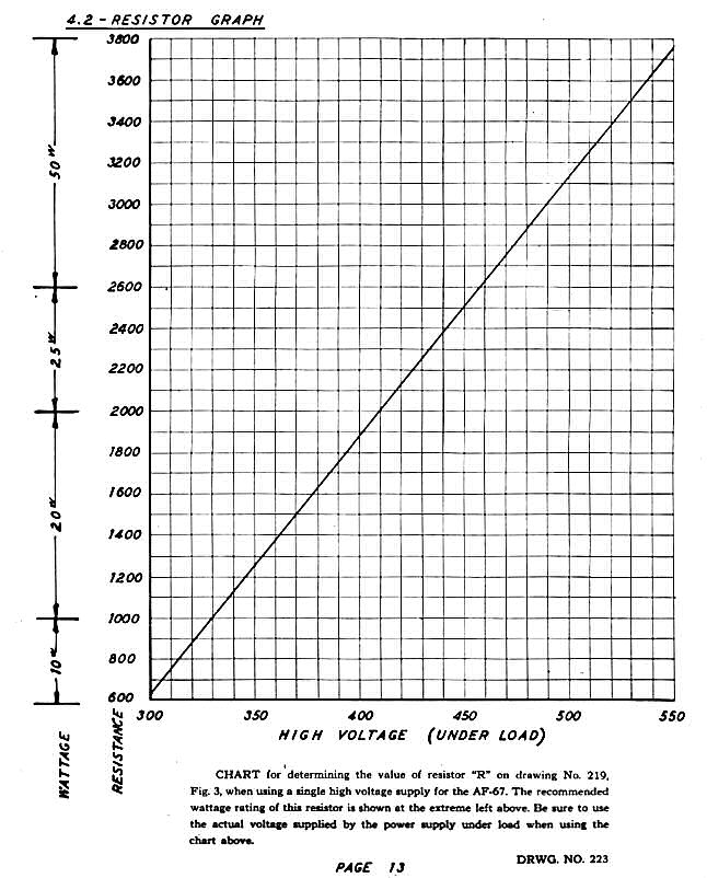
Section 4.2 - Resistor Graph (Drawing 223 - for using a single HV supply)
Section 4.3 - Operating Voltage Chart
Section 4.4 - Control Layout (Drawing 217)
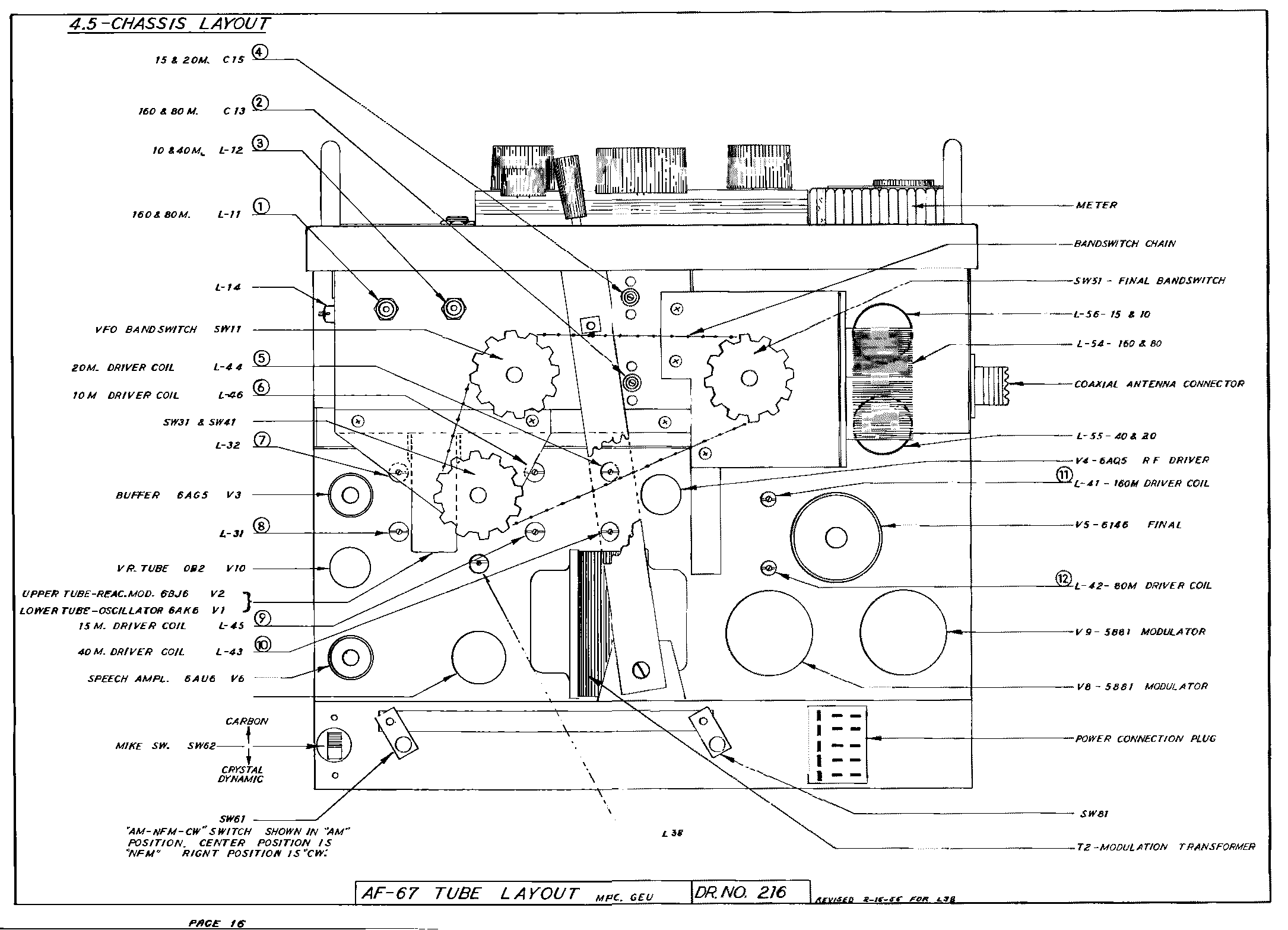
Section 4.5 - Chassis Layout (Drawing 216)
Section 4.6 -
Figure 1, Drawing 219: AF-67 Plug Connection
Section 4.7 - AF-67 Schematic [
1953
] [
1955
]
Drawing 224: PS-2V Power Supply
Hints and Kinks
from QST
Class-B modulator and T/R relay mod
from CQ February 1957
Meter Lamps
from CQ January and May 1958
6 Meter mod
from CQ October 1958
N9BOR Elmac
Additional Notes and Mods
Electric Radio, April 1981,
AF-67 Modulator Fix
, page
28
Electric Radio #189, February, 2005,
Optimizing the Multi-Elmac AF-67 Transmitter
, pages
30 - 35
©2021
WB4KDI Dave J. Barnes
.gif)
.jpg)
.jpg)
.gif)
.gif)