Crude digital interface with acoustic coupling

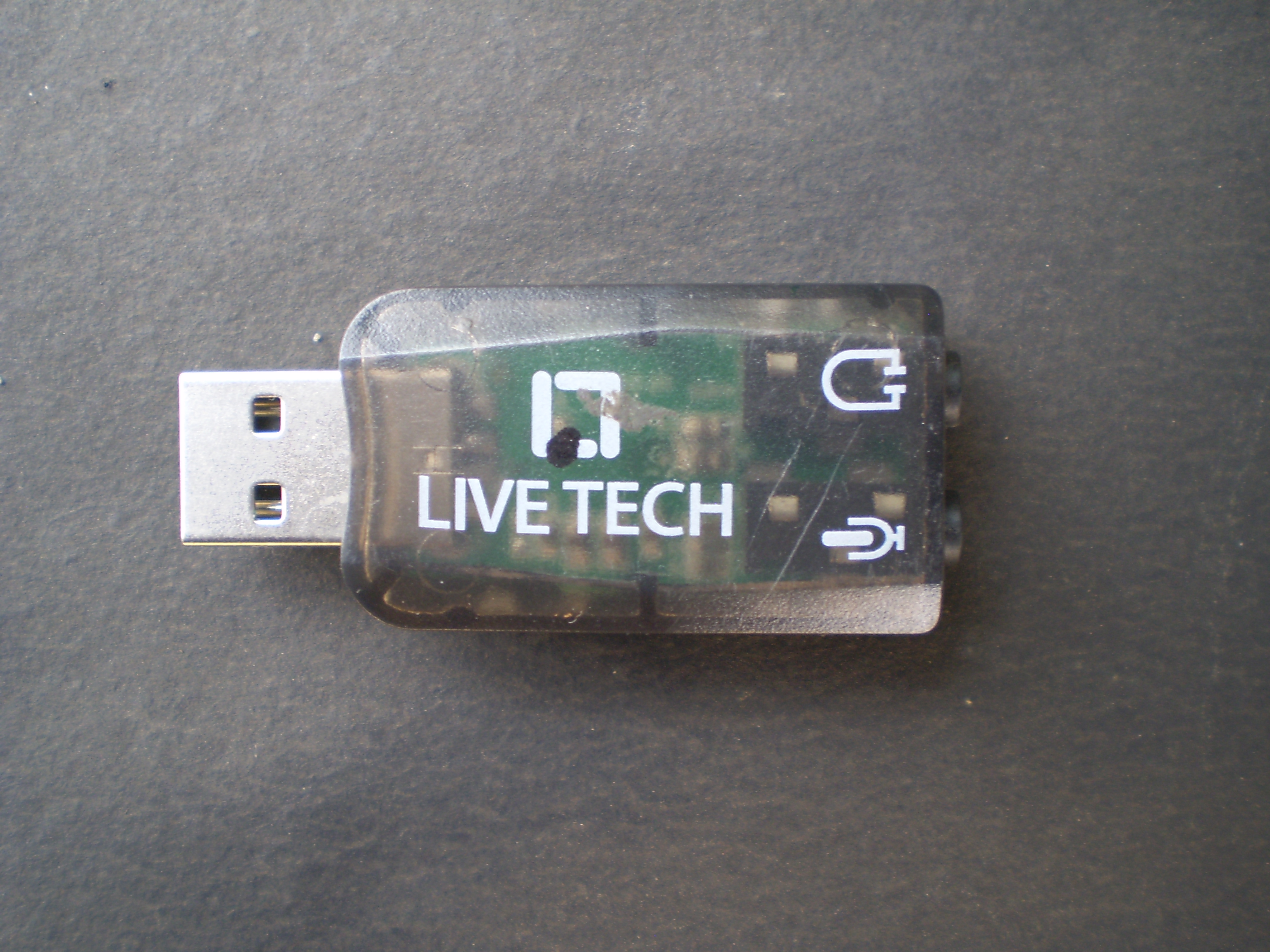
The interface is built around a low cost USB audio adapter, a.k.a. USB external sound card. Here is a picture of one USB external sound card.
USB sound card

Cover of the sound card was removed to take out five connections

 +5 Volt out
 Common point( GND )
 Earphone left channel out
 Earphone right channel out
 Microphone mono input	

This picture shows the connections.
Sound card connections

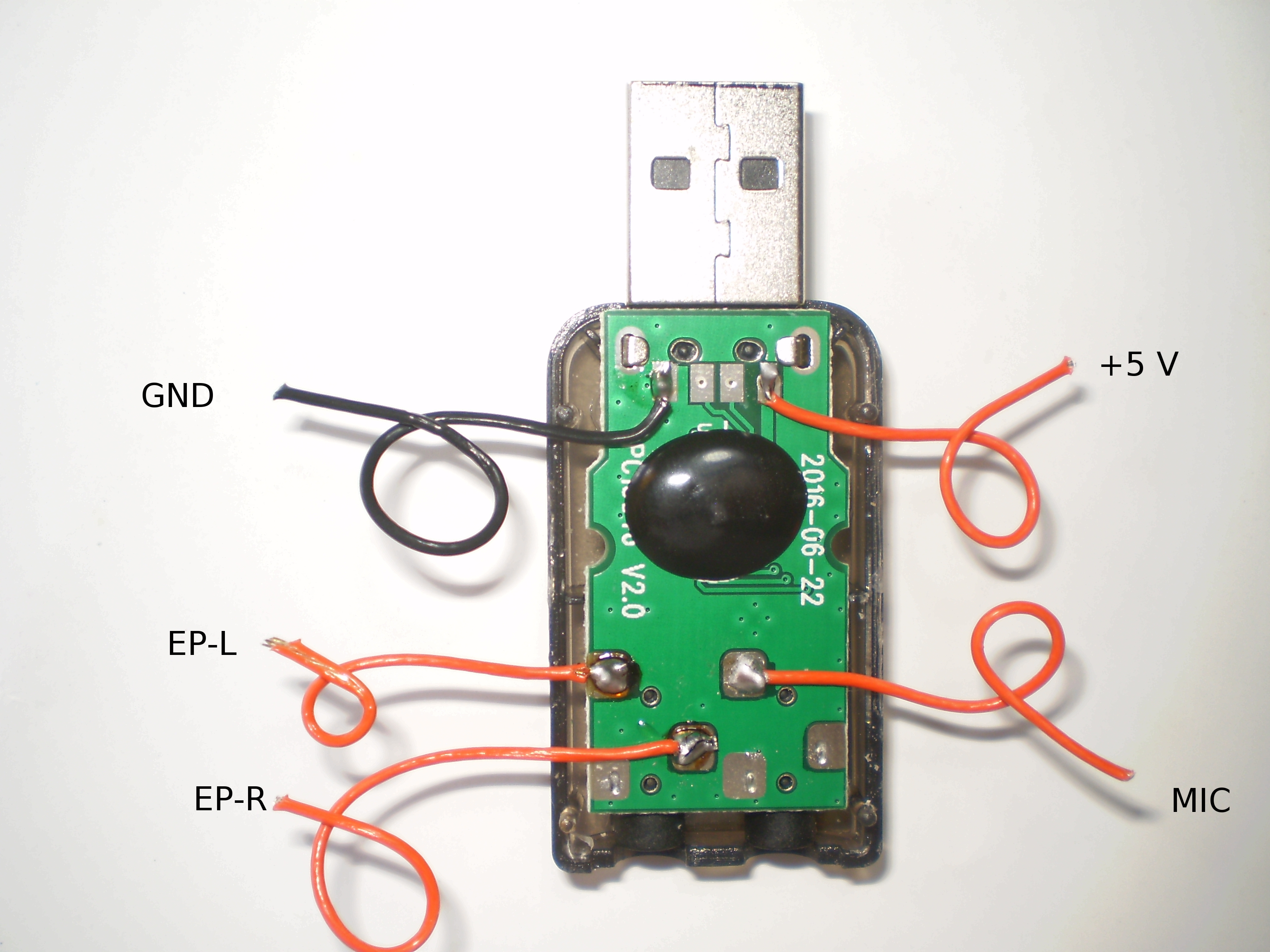
5 Volt is used to power two LM386 amplifiers.
One LM386, amplifies EP-L and drives a speaker. Rig microphone is placed near this speaker to transmit data.
Another LM386 amplifies EP-R for PTT activation. Right channel is used for PTT operation to maintain compatibility with FLDIGI
A low cost electret microphone is connected to microphone mono input. This microphone is placed near rig speaker to read data into sound card. The sound card is connected PC with USB cable. The PC in my case is Raspberry Pi 3 B+ running Raspbian.

Circuit of the interface.
Circuit of interface
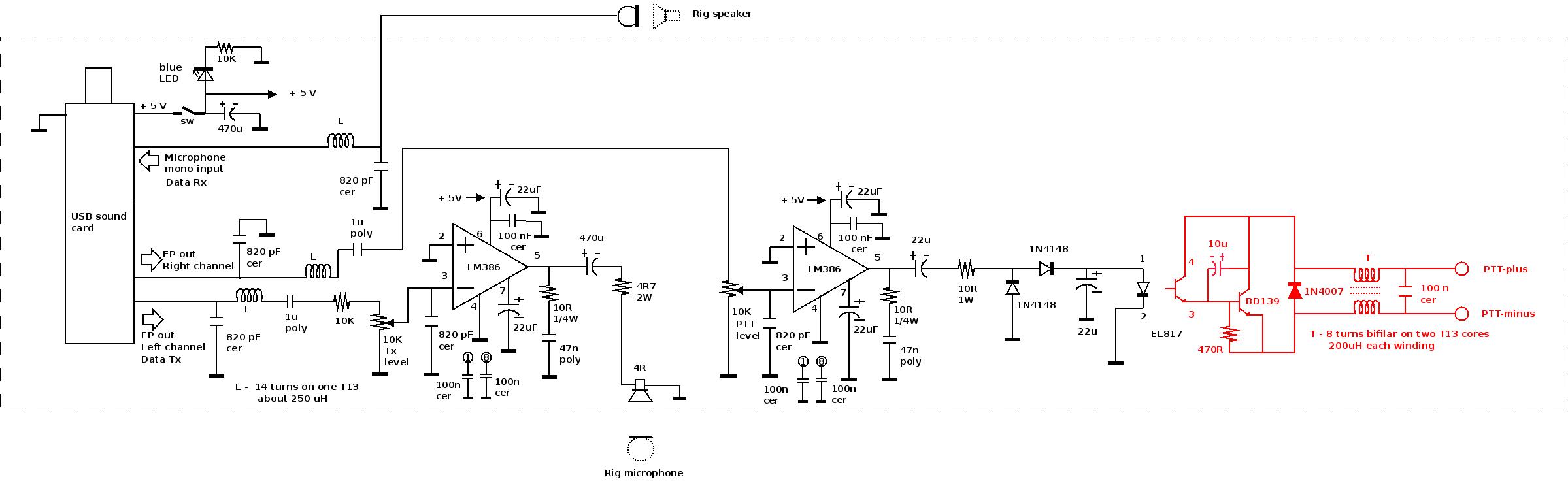
PTT circuit is drawn in red to indicate that it is part of rig (when used ), and is isolated from PC ground.
If VOX is used, all three ( Tx, Rx and PTT ) would be acoustically coupled.

The interface was put inside an aluminium box measuring 23cm x 15.5cm x 6.5cm . A 4 inch speaker was fixed on the lid.
Interface in aluminium box


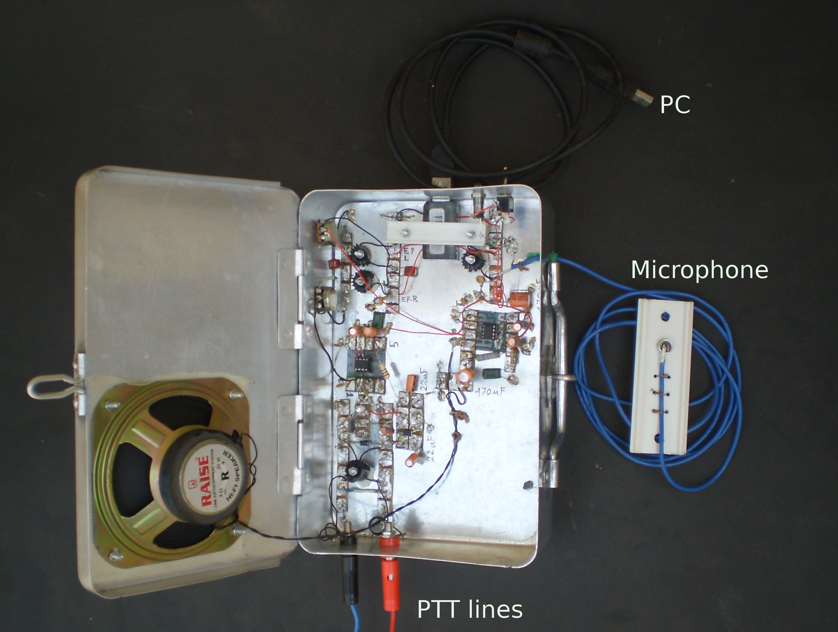
Another picture of the interface.
outside of aluminium box


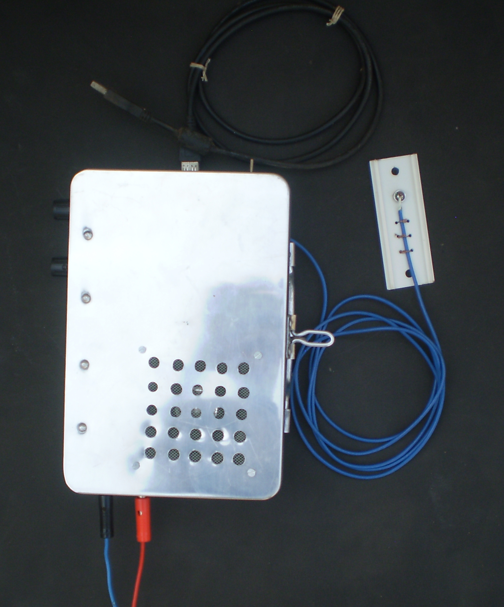
Three inductors(L) and one transformer (T) used T13 ferrite cores.

PTT circuit was tested with four rigs, 20m HB, 40M HB ( modified BITX-40 ), rig made by VU3GTK and ICOM IC-718.


The PTT arrangement of 40M HB ( a modified BITX40 ) is like this and that of 20M HB is nearly same.
40M HB PTT circuit

DC voltage V was measured before and after PTT was triggered by interface.

	Results were:
	-------------------------------
	                 V Volts
	--------------------------------
	           PTT off       PTT on
	--------------------------------
	40M HB     11.66         0.71
	---------------------------------
	VU3GEK      4.85         0.27
	---------------------------------
	IC-718      7.42         0.68
	---------------------------------
				                      		
Socket no.2 and socket no.3 of accessory socket of IC-718 were used for PTT lines. Plug for the accessory socket was not available. A black wire and a red wire were pushed into socket no.2 and socket no.3 respectively. The two wires were connected to black and red sockets as PTT lines.
IC-718 PTT lines

For VU3GEK rig two sockets were fixed on the microphone as PTT lines.
VU3GEK rig PTT lines


This interface has been used for FT8 so far.

Tx level is not flat from 500 Hz to 3 kHz :-(

So a narrow range from 1 kHz to 2 kHz is used for Tx frequency. When Tx frequency is changed Tx level is to be readjusted.

Tried to make PTT lines polarity indifferent with a bridge rectifier.
Polarity indifferent PTT circuit
For IC-718 Voltage came down from 7.4 V to 1.6 V , but it did not switch to Tx.
Other three rigs worked with bridge rectifier.


73 ........ VU2NIL