
This amplifier is the final Tx stage of a homebrewed BITX-40 rig. Objective was to use locally available low cost materials to put together a functional amplifier. Circuit ideas came from Chris Thomson, AC2CZ and others. IRF730 was chosen over IRF510 for its higher breakdown voltage, though its input capacitance is higher. For a low end 40m only amplifier this was OK. A higher drain voltage was chosen to push down output capacitance of IRF730. Two driver stages used IRF510.
Ugly construction was used to make the amplifier. Paper phenolic boards covered with thin galvanised iron sheet were used as base. The GI plates served as common ground. Components were fixed on small pieces of single sided copper clad glass epoxy PCB material.
Two driver stages used IRF510 (Q1 and Q2 ).
Q1 and Q2 were mounted on a 4 inch x 2.5 inch heat sink.
The push-pull output stage used a pair of IRF730 ( Q3 and Q4 )
Q3 and Q4 were mounted on a 5.25 inch x 6 inch heavy heat sink.
Two resistors are not shown in the circuit diagram. A 100 K resistor was connected from each gate of Q3 and Q4 to ground to prevent floating gates.
Circuit of the amplifier.
Values of inductors and variable capacitor were measured with home brewed instrument. The values
are approximate. Input is shown as 250 mV. This can be off by 200% or more :‑(
Some available components were unsuitable for a particular task. As an example, polyester film
capacitors were used for decoupling of 75 Volt DC supply, as high voltage ceramic capacitors were not
available.
A 6A10 rectifier was used for reverse polarity protection.
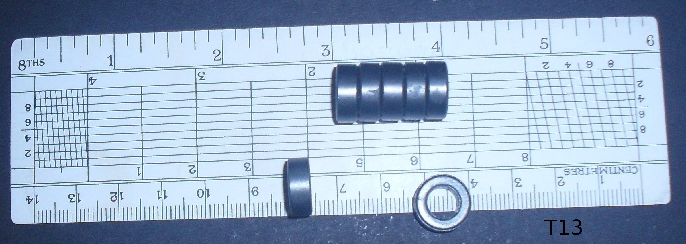
Ferrite toroids called T13 by component retailers, were available locally.
Specifications are however unknown. Resistance between opposite ends of a toroid varied from 2K5 to 60K
from unit to unit : ‑(
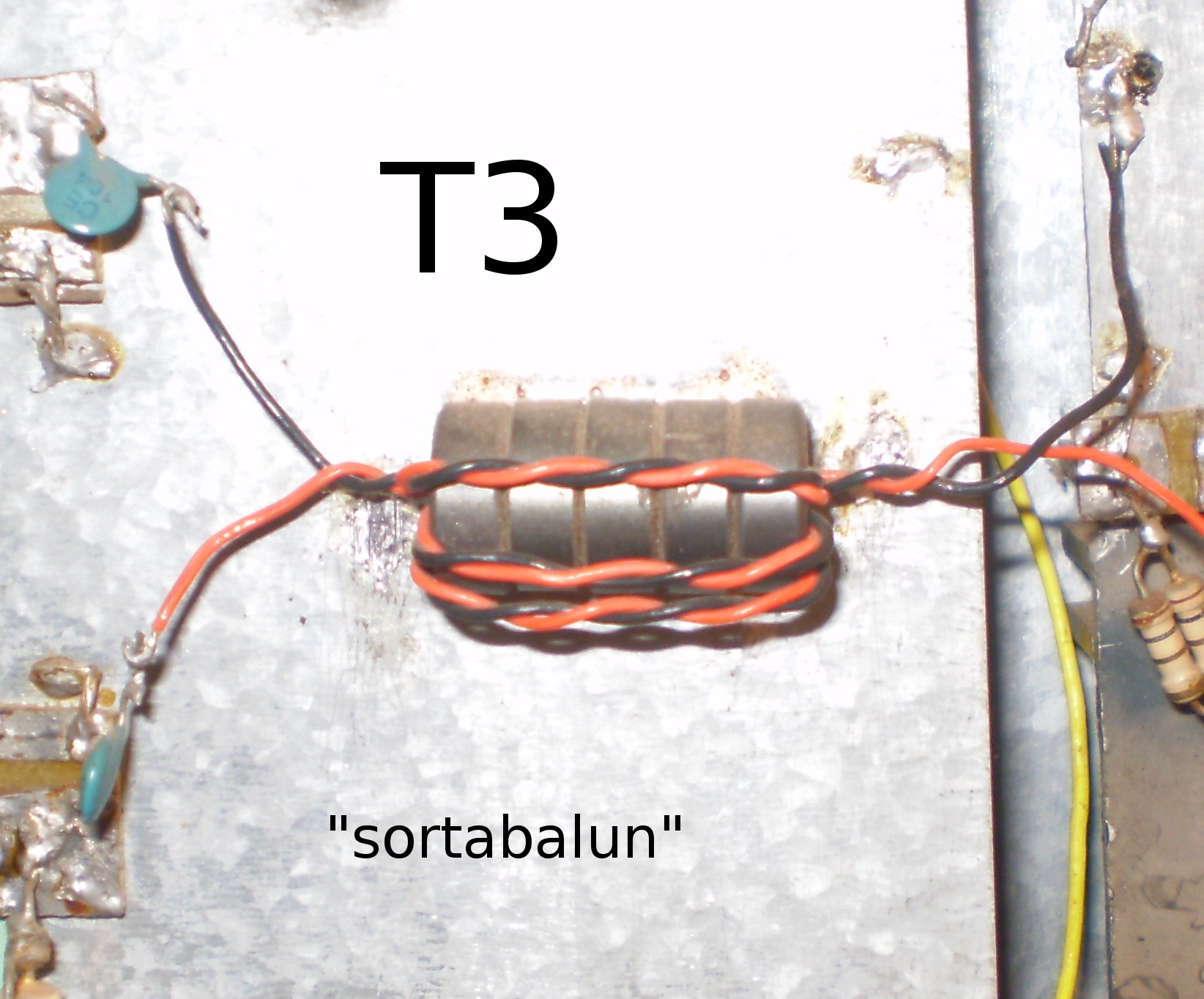
These were used as core of RFC, 4:1 transformers and "sortabalun" .
Here is a picture of T13 cores.
T3 was made with three turns on five T13 cores.
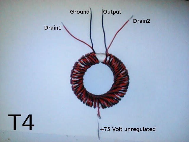
Toroids of 43 material ferrite were not available, so plastic toroid was used as core of output transformer T4. Four curtain rings were used to make the plastic toroid. The steps of construction are explained with a few pictures.
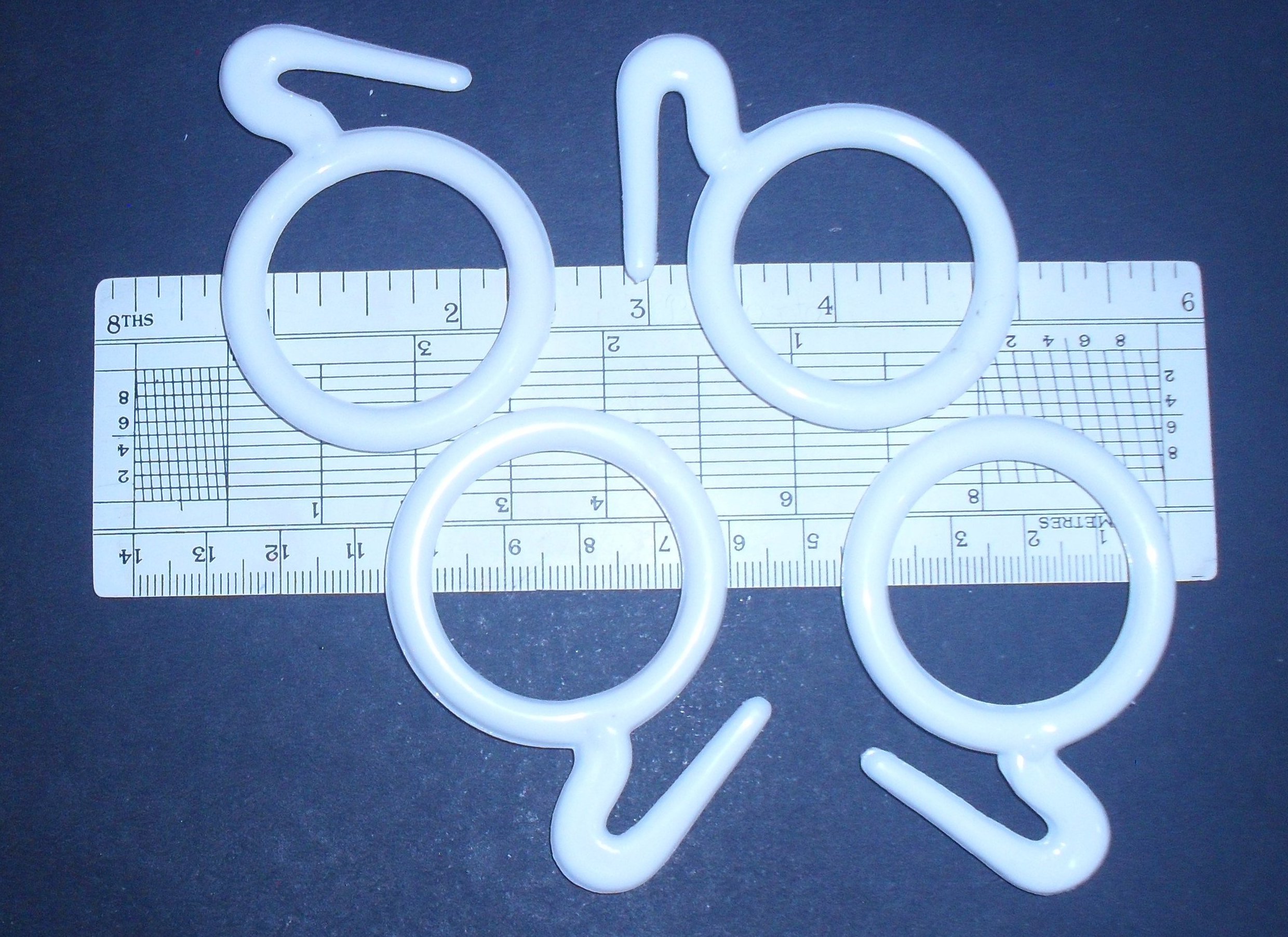
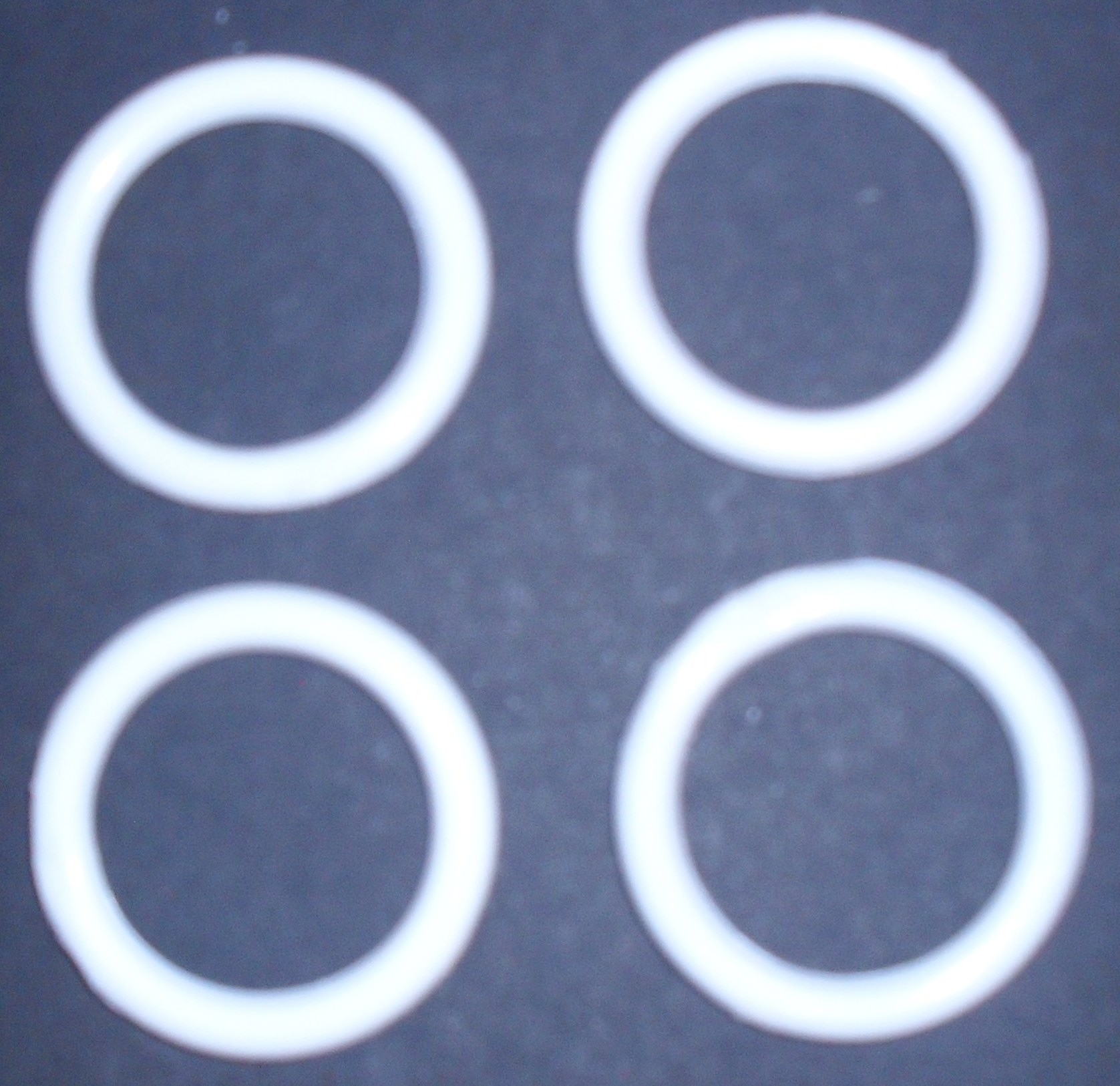
Adjacent rings were joined by melting three spots along the circumference with hot pointed piece of iron.

Holes were made in the plastic toroid with the hot pointed iron for the two ends of the winding.

No longer making plastic toroid this way. 25 mm. pieces of 48 mm. OD. plastic water pipe are now used as toroid. Holes are drilled on it to remove some plastic to reduce loss.
Teflon covered red and black wires were twisted together using a power drill, to make
bifilar wire.There were about four twists per inch. 55 turns could be accommodated
on the toroid with the bifilar wire. Odd number of turns were used to get a centre-tap.
Twelve feet six inch bifilar wire was used, including two, three inch end pieces.
Red wire was cut at the middle of the winding. The cut ends were soldered for feeding
positive of unregulated 75 Volt for the two drains.
During winding, wished for suitable hollow Teflon toroid with circular cross section!

Transformer T4 looked like this.
The bare-bones power supply is unregulated. It has a companion, a current limiter. Both circuits are stupid, their smart feature is low cost.
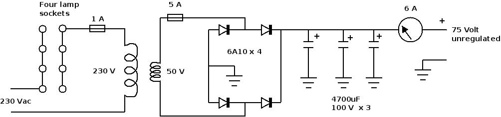

The current limiter has four lamp sockets to take in four lamps.
The power supply is never used without the current limiter. Though 6A10 rectifier has adequate surge current
capability, some inrush current limiting by incandescent metal filament lamp ( PTC ), keeps current through
6A10 to a safe value. This would also allow to add another bank of three 4700uF filter capacitors in future.
It also limits current during mismatch.
One 60 Watt lamp is used to check for short circuits.
Two 200 Watt lamps are used during adjustment of no signal currents of Q3 and Q4.
Two to four 200 Watt lamps are used during QSO.
The mains voltage, 230 Vac IS LETHAL. The exposed lamp socket pins pose grave danger. The power supply and current limiter must be kept somewhere out of reach of children. When not in use, current limiter should be unplugged from wall socket.
Power output was measured with a 50 ohm dummy load and RF probe.Dummy load was connected between
TP2 and ground.
Harmonic energy in the power output could not be estimated due to lack of understanding of what is involved
and instruments, in that order.
Adjustments:

A 60 Watt lamp was used to limit current when 75 volt
was applied for the first time.

(a) Power supply to the amplifier is removed.
    Loop1 is removed.
    RF probe is connected to TP2.
    7100 kHz signal is fed at TP1. Level of signal is
    adjusted to get a reading of about 10 mV.
    Capacitor C1 is varied to get a peak reading.
    Signal is removed from TP1; RF probe is removed from TP2.
    Loop1 is replaced.

(b)
    Input drive is disconnected at the input of 3 dB pad.
    Loop2 is removed and a current meter is connected in
    its place with the indicated polarity.
    Q4 drain connection is broken.
    Two 200 Watt lamps are used to limit current.
    75 Volt and 12 Volt supply are connected.
    PTT is pressed to get Q3 no signal current.
    Resistors are paralleled with R3(3K9) to set 300mA in Q3.
    ( 3K9 || 2K7 ) gave 320mA in Q3.

(c)
    Q3 drain connection is broken and Q4 drain connection is put back.
    PTT is pressed to get Q4 no signal current.
    Resistors are paralleled with R4(3K9) to set 300mA in Q4.
    ( 3K9 || 6K8 || 33K ) set  330mA in Q4.
    Q3 drain connection is restored.

(d)
    75 Volt supply is removed and 12 supply is kept ON.
    Q1 and Q2 no signal drain current are estimated by
    measuring voltage drop across source
    resistors ( 0R5 ).
    Resistors are paralleled with R1(3K3) to set 150mA in Q1.
    ( 3K3 || 47K ) was used to get 160 mA in Q1.
    R2 = 100R produced; 930mA in Q2.
    Input drive is reconnected at the input of 3 dB pad.
The amplifier was operational in December 2016 on 40m SSB LSB with horizontal loop antenna and a link coupled tuner. BITX-40 was built as LSB only set, this created problem later for FT8 communication.
Suitable capacitors were not available to build LPF after the power amplifier.
Generated harmonic is dissipated in seven paralleled 1K/2W resistors. A 7 mHz parallel resonant circuit was used to keep out 7 mHz in this path.
300mA in each IRF730 with 75 Volt drain voltage is considered to be high. Drain voltage comes down to nearly 50 Volt when signal is applied. With 50 Volt drain voltage, 300mA is still on the higher side. Assumed lesser harmonic generation with higher standing current. Without LPF, harmonics are attenuated by two tuned circuits of the antenna tuner and a parallel resonant circuit at 7.1 mHz.
The reports are mixed, some good( 59+ ), some bad( 44 ), no copy, distorted audio, clear audio etc etc. Local reports are mostly good.
Some of the photographs were taken by my friend Pankaj Kar.
73 ........ VU2NIL