

Then there's the construction side of things, I believe in the KISS principle...Keep..it..Simple...Stupid! You can spend a lot on vacuum capacitors and large diameter copper pipe that costs a fortune to roll into a circle. Or do what I do and use the loop itself and thin air to form a capacitor. My way is harder to tune, though not always, but it sure is cheaper. Just make the loop as big as is practical, to maximize bandwidth. If its circumference is near or longer than a quarter wave, the purists may say it's not a true small transmitting loop, but it will work better anyway!
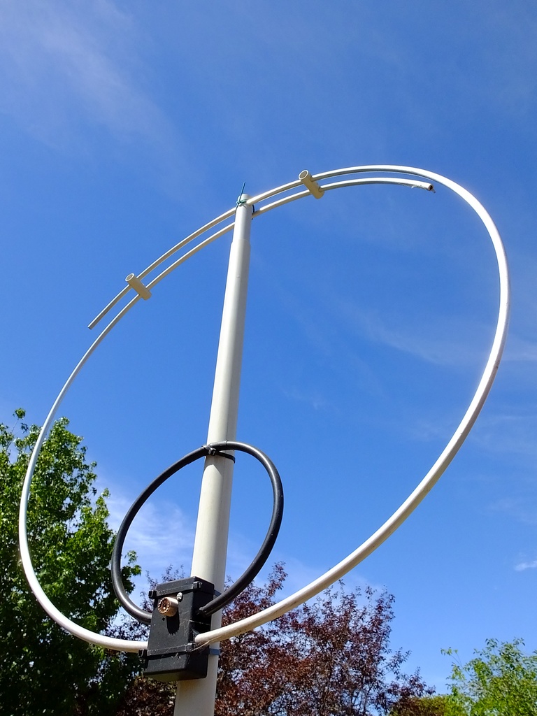
At right is my 10 mtr magloop, its diameter is 800 mm, so the circumference is about 2.5 mtrs, the overlap is about 820 mm. It was made from a 3.5 mtr length of 10 mm aluminium with a wall thickness of around 1.7 mm. The ends don't bend very well, so I chopped them off.
My aluminium bends nicely around a 200 liter drum, however, it's thicker wall and slightly softer grade may be hard to find these days. Mine was purchased several years ago as scrap from a company that no longer makes it.
Hi everyone, I've been messing around with these antennas for long enough now to have formed a few opinions on them.
Firstly, there is no doubt in my mind that they really do work.... and work well!
On 40 mtrs, compared to my longwire, which is optimized for that band,and under the usual mostly good conditions, the difference is less than 10 dB, both antennas showing 9+ or better. For all practical purposes, they both work well. At other times, it really is up to the band conditions as to which will work best.
The Magloop has some real advantages over the much larger fixed antenna. It can be rotated to null out some noise, this can be more important than gain at times.
It's not that difficult to change polarization. When the loop is vertical, it's verticaly polarized along the line of the loop at all vertical angles, and smaller horizontal lobes at 90 degrees to the plane of the loop at mostly high angles. When it's laid flat, polarization is mostly horizontal.To get a low takeoff angle with the flat loop it must be at a similar height as would a horizontal dipole. I have found in practice that the higher the horizontal loop is, the better it works, even the SWR bandwidth is greater.
If you can find some tubing that you think may be suitable, then bend it on a hot day, or arrange for some warming by other means, but if the warming is not evenly done , I really think you may end up with a messy bend.
There are, however, alternatives...make, buy or hire a tube roller...use flat bar, not as easy to bend neatly as you may think, but will roll quite well. It may be better though, to make an octagonal loop from flat bar that looks neat and also works well.
About the Capacitor.
As you can see from the photo, there is an overlap of about 820 mm at the top, that's the capacitor. Since the loop, in terms of wavelength is quite large on 10 mtrs, it takes little capacitance to resonate it. There is more than enough provided by the overlap, adjust the spacing, adjust the capacitance. With a paper thin gap between the two sections of tubing, it will hear on 20 mtrs reasonably well, but transmit, forget it!
On 15 mtrs this antenna is practical, but 100 watts may be a bit much as the spacing is still rather small. For 10 and 12 meters though, this antenna shines!
As the spacing at the center of the overlap is fixed, and the two outside spacers have a different spacing, sliding them along the tubing will vary the spacing and hence, the capacitance also. On 10 mtrs I can operate over all the band section that interests me without changing the setting at all. This is because the loop is quite large at 28.5 mhz, so the bandwidth is also large. Of course this approach needs to be modified somewhat for use on the lower bands, capacitance must be added. If you make your loop from flat bar, it's easier and more efficient as the extra surface area means more capacitance.
A few thoughts on Magnetic Loops
A 40 Meter Loop
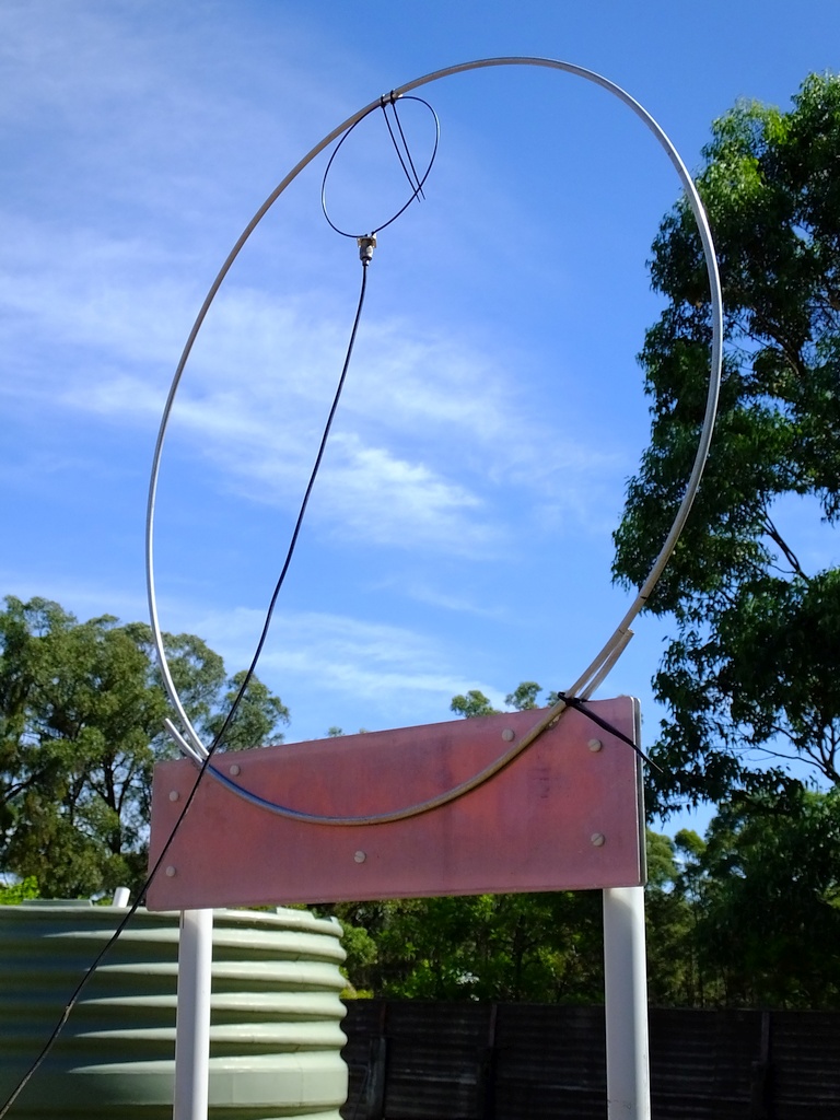
The loop on the right is only 1 meter in diameter, it was sized to fit in my car, otherwise I would have made it larger, a 2 meter diameter loop would be a good choice if it is practical for you to build. The larger loop would have a circumference of 6.28 meters. I have built a rectangular loop 2 meters tall and 1 wide, that's the same circumference in a more practical shape using easy to get materials.
For that antenna I used 25x25 mm channel section as it has more surface area than square, but it's not as stiff, which eventually led to it's destruction, so if I did that one again I would use square tubing, though maybe a larger size, the bigger the better here.
Construction article will follow later.

VK2YOC

Blog

Magnetic Loops.