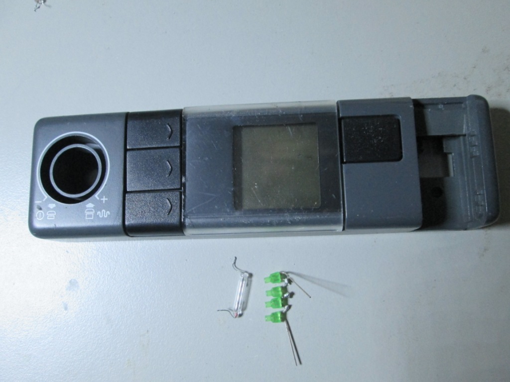
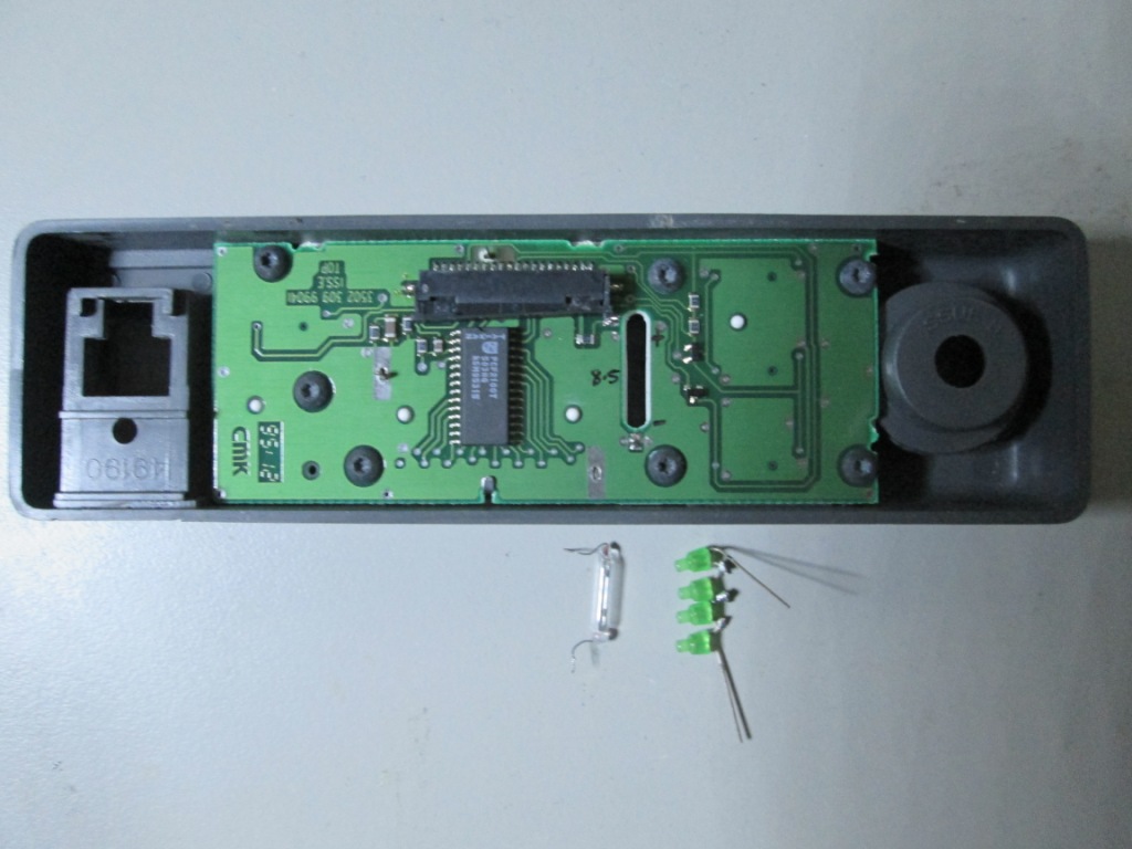
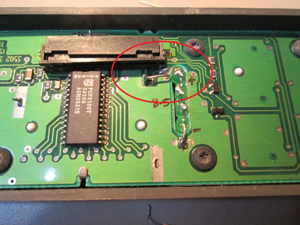
Matt VK3VS (VK3SMB)'s PRM80 conversion to 6 metre Amateur band page ******************************************************************************************************************** Replacing the incandescent globes in the PRM-80 heads for the LCD backlighting. The globes die after some time and you will not find any replacements, so I removed and converted to green LEDs, I used some miniature gree LEDS, that run nicely at 2.1v @ 16mA each. The LEDs will draw less power and reduce the heat build up in the head, that way I still get backlighting for the LCD display with less current drawn and less heat produced. For the 10 Channel head, it used a long tube globe, fed by 8.5v via a 220 ohm resistor, since there was space where the long tube globe had been I soldered four LEDs in series to provide the 8.4v drop, therefore I coiuld bypass the 220 ohm resistor. When you bend the cathode end of the LED array, bend it around to keep it away from the plastic flat cable connector so you still disconnect the cable . First photos shows the 10 channel head and the old tube globe and the new four LED array, followed by photo of the LEDs during installation.
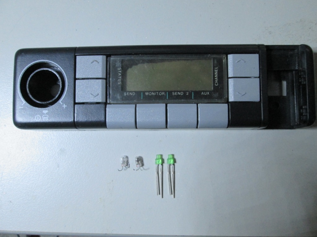
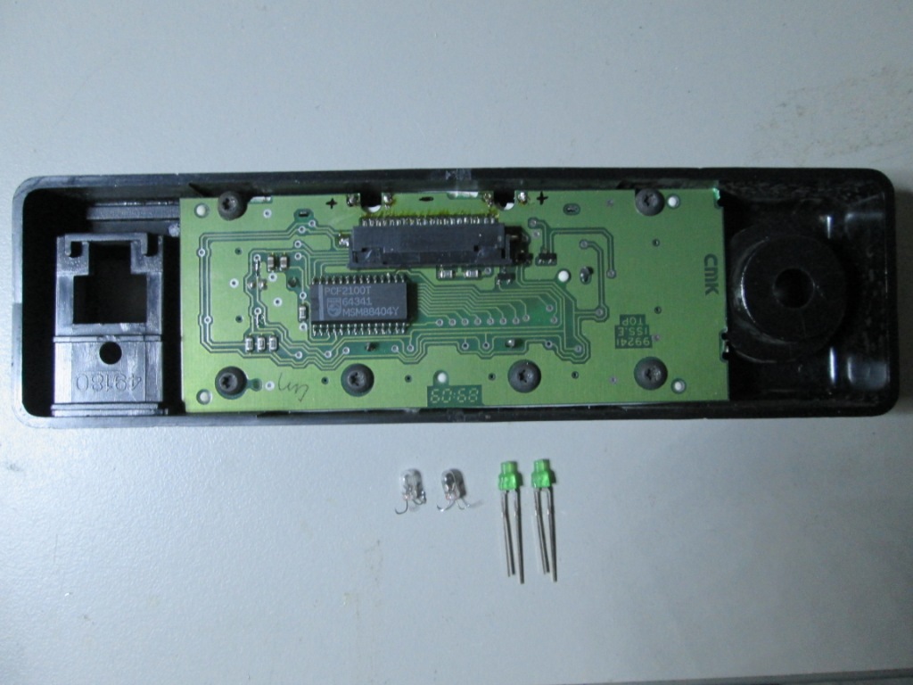
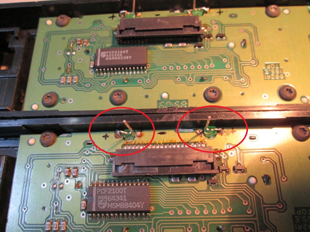
For the 61 channel head, it used two globes, each fed via their own 22 ohm resistor, since these are normla shaped globes I could only replace with a single LED. With the calculations based on 2.1v @ 16mA, I needed about 440 Ohm, as there was already 22 Ohm, I only needed about 420 Ohm to be added in series, which I did. I also filed down the LED bezel to put a sloping face directing the light from the LED towards the LCD glass. On the 10 channel head I could have done this, but with four LEDs it had enough light sprayed to backlight the LCD nicely. With this head and just two LEDs it was not as lit as I had hoped, but enough to see the the display in total darkness. The anode end of the LED gets bent over, trimmed and the resistor folded to solder the anode end of the LED and to the existing ground solder spot. These photos show the 61 channel head with old globes and new LEDS followed by photo of the LEDs installed
********************************************************************************************************************